Building decoration auxiliary supporting device for building construction

A technology for architectural decoration and auxiliary support, which is applied in the directions of architecture, building structure, housing structure support, etc., can solve the problems of difficult operation of the lifting mechanism to change the height, difficult support effect of the support plate, troublesome operation process, etc., to improve construction efficiency, The effect of improving safety and changing the construction location

Inactive Publication Date: 2021-03-26
天长市市政建筑有限责任公司
View PDF5 Cites 3 Cited by
  • Summary
  • Abstract
  • Description
  • Claims
  • Application Information

AI Technical Summary

Problems solved by technology

[0003] Although the current auxiliary supporting device for architectural decoration can adjust the height, the lifting mechanism provided by the device requires manual operation, and the operation process is cumbersome. In addition, during the working process, due to the heavy upper mechanism, it is difficult to operate the lifting mechanism to change the height. The practicability is low, and at the same time, when actually supporting the architectural decoration, due to the different sizes and angles of the architectural decoration, it is difficult for the support plate whose angle and position cannot be adjusted by the existing device to play a good supporting effect, and the architectural decoration support often needs a certain amount of support. The pre-tightening force makes the architectural decoration better adhere to the wall surface, while the existing devices rely on the bolt clamping to provide effective support pre-tightening force for the architectural decoration.

Method used


Image

  • Building decoration auxiliary supporting device for building construction
  • Building decoration auxiliary supporting device for building construction
  • Building decoration auxiliary supporting device for building construction

Examples


Embodiment Construction

[0024] The following will clearly and completely describe the technical solutions in the embodiments of the present invention with reference to the accompanying drawings in the embodiments of the present invention. Obviously, the described embodiments are only some, not all, embodiments of the present invention. Based on the embodiments of the present invention, all other embodiments obtained by persons of ordinary skill in the art without making creative efforts belong to the protection scope of the present invention.

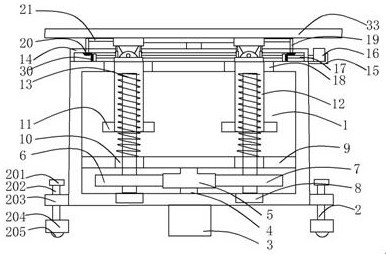
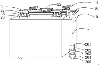
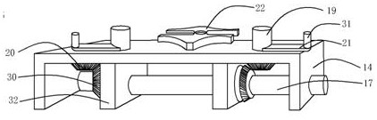
[0025] see Figure 1-7 , the present invention provides a technical solution: a building decoration auxiliary support device for building construction, including an operation box 1 containing a cavity, the lower part of the inner side wall of the operation box 1 is fixedly connected with a fixing plate 9 that is compatible with the cavity, The upper surface of the fixed plate 9 is provided with two symmetrical first through holes 10, and the inner bottom wall ...


PUM


Abstract

The invention discloses a building decoration auxiliary supporting device for building construction. The device comprises an operation box with a cavity, a fixing plate matched with the cavity is fixedly connected to the lower portion of the inner side wall of the operation box, two symmetrical first through holes are formed in the upper surface of the fixing plate, two symmetrical bearings are fixedly inlaid in the inner bottom wall of the operation box, threaded rods are fixedly connected to inner rings of the bearings, and a second suction cup is connected to the bottom surface of a workbench. According to the building decoration auxiliary supporting device, a worker stands on the upper surface of the workbench to conduct construction, when the height of the workbench needs to be increased or decreased, a first gear is driven to rotate, and the threaded rods are driven to rotate through meshing connection between a second gear and the first gear and meshing connection between a third gear and the first gear, and the threaded connection between the threaded rods and the first through holes is utilized to drive the workbench to perform lifting adjustment, so that the lifting adjustment of the workbench can be realized, the advantage of convenience in adjustment is achieved, the construction efficiency is improved, and the problems that the height of a workbench is relatively fixed and is inconvenient to adjust are solved.

Description

technical field [0001] The invention relates to the technical field of architectural decoration auxiliary support mechanical equipment, in particular to an architectural decoration auxiliary support device for building construction. Background technique [0002] Architectural decoration is the abbreviation of architectural decoration and decoration engineering. Architectural decoration is to protect the main structure of the building, improve the physical performance of the building, use the function and beautify the building. The brackets erected for buildings or buildings are generally used on the construction site for exterior walls, interior decoration and places where the height of the storey cannot be directly constructed. For example, during the construction process, when decorating the ceiling in the building, the decorations Use glue to bond on the roof. Before the glue is completely solidified, the decoration should be tightly against the roof to avoid weak bonding...

Claims


Application Information

Patent Timeline
Patent Type & Authority Applications(China)
IPC IPC(8): E04G1/18E04G1/15E04G1/24
CPCE04G1/15E04G1/18E04G1/24E04G2001/242
Inventor 王志东
Owner 天长市市政建筑有限责任公司
Why Eureka
Try Eureka