Magnetron sputtering coating system

A magnetron sputtering coating and sputtering chamber technology, applied in the field of magnetron sputtering, can solve the problems of inability to clean up impurity gas and unfavorable process stability.

Active Publication Date: 2014-06-18
WGTECH JIANGXI
View PDF7 Cites 2 Cited by
  • Summary
  • Abstract
  • Description
  • Claims
  • Application Information

AI Technical Summary

Problems solved by technology

However, due to the continuous inflating of the film-in transition chamber and the film-out transition chamber, the film-in transition chamber and the film-out transition chamber cannot effectively pump out the impurity gas, which is not conducive to the stability of the process.

Method used


Image

  • Magnetron sputtering coating system
  • Magnetron sputtering coating system

Examples


Embodiment Construction

[0020] In order to make the above objects, features and advantages of the present invention more comprehensible, specific implementations of the present invention will be described in detail below in conjunction with the accompanying drawings. In the following description, numerous specific details are set forth in order to provide a thorough understanding of the present invention. However, the present invention can be implemented in many other ways different from those described here, and those skilled in the art can make similar improvements without departing from the connotation of the present invention, so the present invention is not limited by the specific implementations disclosed below.

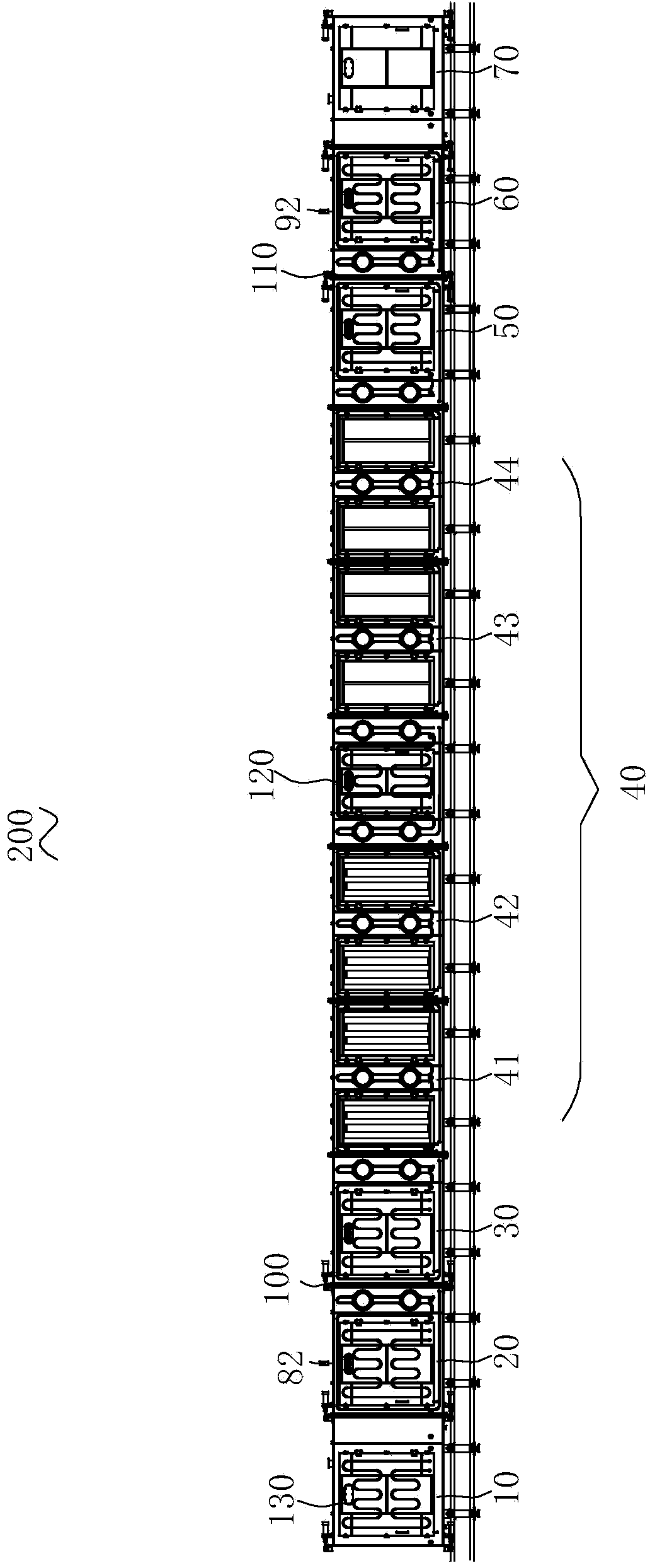
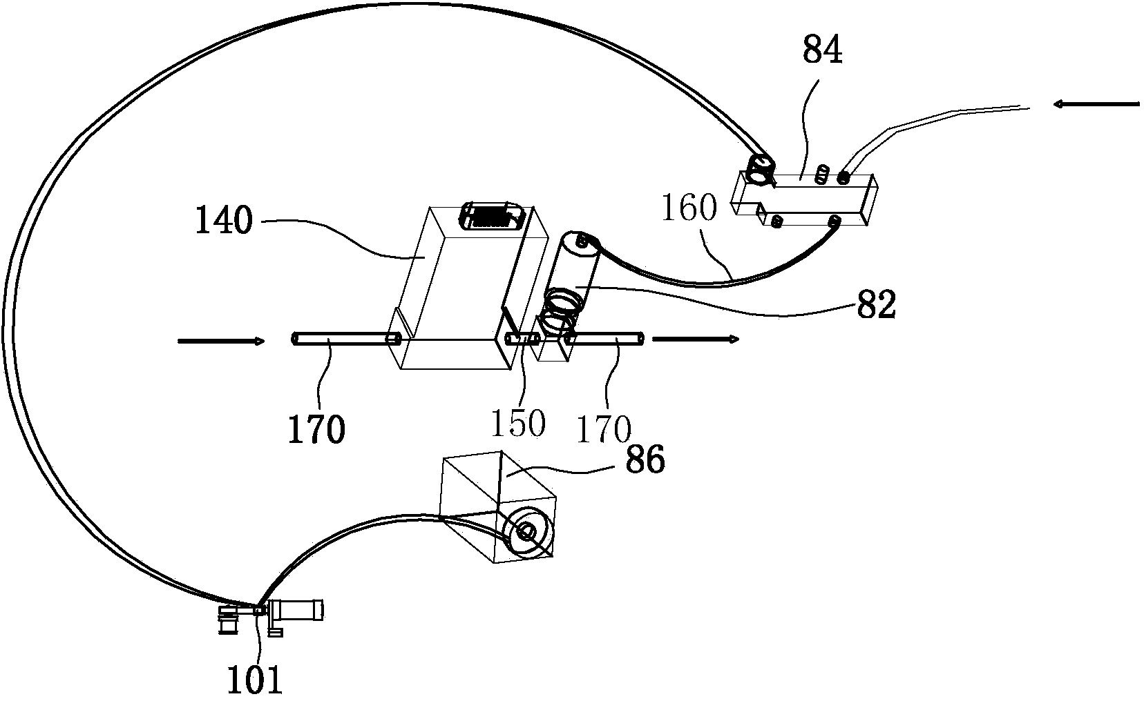
[0021] see figure 1 , a magnetron sputtering coating system 200 according to an embodiment, comprising a film feed chamber 10, a film feed transition chamber 20, a film feed buffer chamber 30, a sputtering chamber 40, a film discharge buffer chamber 50, a film discharge transition cha...


PUM


Abstract

The invention provides a magnetron sputtering coating system. The magnetron sputtering coating system comprises a first intermittent inflation assembly, a second intermittent inflation assembly, a substrate feeding chamber, a substrate feeding transition chamber, a substrate feeding buffer chamber, a sputtering chamber, a substrate discharging buffer chamber, a substrate discharging transition chamber and a substrate discharging chamber, wherein a first gate valve is arranged between the substrate feeding transition chamber and the substrate feeding buffer chamber, and a second gate valve is arranged between the substrate discharging transition chamber and the substrate discharging buffer chamber; the first intermittent inflation assembly comprises a first intermittent switch, a first intermittent switch electromagnetic valve and a first delayer, and the first intermittent switch is arranged on the substrate feeding transition chamber; the second intermittent inflation assembly comprises a second intermittent switch, a second intermittent switch electromagnetic valve and a second delayer, and the second intermittent switch is arranged on the substrate discharging transition chamber; the first intermittent switch electromagnetic valve is connected to the first gate valve in parallel, and the first delayer is connected to the first gate valve in series; the second intermittent switch electromagnetic valve is connected to the second gate valve in parallel, and the second delayer is connected to the second gate valve in series. The magnetron sputtering coating system can be used for solving the problem of gas wasting and facilitating technology stabilization.

Description

technical field [0001] The invention relates to the technical field of magnetron sputtering, in particular to a magnetron sputtering coating system. Background technique [0002] Magnetron sputtering coating method is a coating method commonly used in coating at present. Before magnetron sputtering coating, pumping is required to remove impurity gases and make the system reach a certain degree of vacuum. During coating, in order to balance the pressure of the sputtering chamber, the process gas is often filled in the film-in transition chamber and the film-out transition chamber, so that the pressure of the film-in transition chamber and the pressure of the sputtering chamber are balanced, and the pressure of the film-out transition chamber The vacuum is balanced with the pressure of the sputtering chamber. [0003] However, in the current magnetron sputtering coating system, in order to balance the pressure of the sputtering chamber, only the film-in transition chamber an...

Claims


Application Information

Patent Timeline
IPC IPC(8): C23C14/35
Inventor 郑芳平张迅易伟华
Owner WGTECH JIANGXI
Why Eureka
Try Eureka