
Formation Density Discrimination Method for Carbonate Natural Gas Formation

A technology of formation density and carbonate rock, applied in wellbore/well components, earthwork drilling and production, etc., to improve the discrimination effect and have a good application prospect

Inactive Publication Date: 2017-01-25
CHINA NAT PETROLEUM CORP CHUANQING DRILLING ENG CO LTD
View PDF5 Cites 0 Cited by
  • Summary
  • Abstract
  • Description
  • Claims
  • Application Information

AI Technical Summary

Problems solved by technology

[0005] The present invention aims to solve the technical problems in the above-mentioned prior art that it is impossible to discriminate natural gas layers in complex lithologic formations, especially carbonate rock formations, and provides a method for discriminating density of carbonate rock natural gas formations. The invention is especially suitable for use in the identification of natural gas layers in carbonate rock formations, has a good application prospect, and improves the identification effect of natural gas layers

Method used


Image

  • Formation Density Discrimination Method for Carbonate Natural Gas Formation
  • Formation Density Discrimination Method for Carbonate Natural Gas Formation
  • Formation Density Discrimination Method for Carbonate Natural Gas Formation

Examples


Embodiment 1

[0041] As the best implementation mode of the present invention, it uses carbonate rock mineral composition, porosity, water saturation, formation resistivity and formation water resistivity factors to calculate a formation density theoretical value curve, and the formation density theoretical value obtained by calculation The natural gas layer can be identified according to the difference between the two curves and the measured formation density curve.

[0042] The specific method of "calculating a theoretical value curve of formation density by utilizing carbonate rock mineral composition, porosity, water saturation, formation resistivity and formation water resistivity factors" is as follows:

[0043] a. Experimentally determine rock-electricity parameters

[0044] The cored rock samples were subjected to rock electrical experiments under simulated formation conditions to obtain the rock cementation index m, water saturation index n and coefficients a and b, and at the same...

Embodiment 2

[0066] As a verification example of the present invention, with reference to the accompanying drawings in the description:

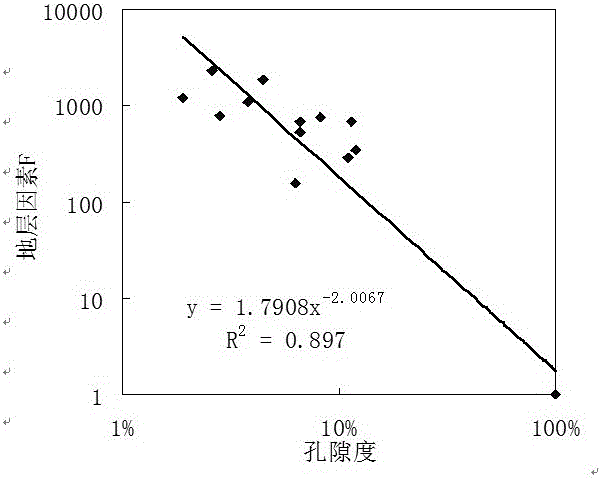
[0067] figure 1 The intersection diagram of formation factors and porosity obtained from the results of lithoelectric experiments on carbonate rock formations in a certain block. The lithoelectric experiments were carried out under the conditions of simulated formation temperature, formation pressure and formation water salinity. According to the experimental results, the cementation Index m=2 and a=1.8.

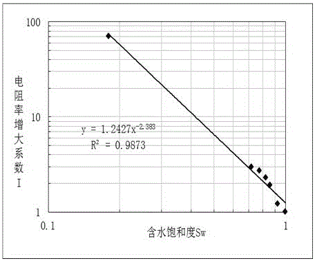
[0068] figure 2 It is the cross plot of resistivity increase coefficient and water saturation obtained from rock electric experiment, and the saturation index n=2.4 and b=1.2 are obtained according to the experimental results.

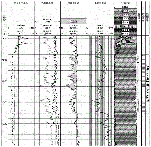
[0069] image 3 It is the discriminant map of carbonate gas layer in a certain well in this area. The first track in the figure is the depth, the second, third, and fifth are the original logging curves; the fourth track i...


PUM


Abstract

The invention discloses a method for distinguishing the formation density of a carbonatite natural gas reservoir, and belongs to the application technology field of density logging information. The factors of carbonatite mineral components, porosity, water saturation, formation electrical resistivity and formation water electrical resistivity are used, a formation density theoretical value curve is calculated, the formation density theoretical value curve obtained through calculation and an actual measured formation density curve are compared, and the natural gas reservoir is distinguished according to the difference features of the formation density theoretical value curve and the actual measured formation density curve. The method is particularly suitable for distinguishing the natural gas reservoir in carbonate formations, is good in application prospect, and improves the distinguishing effect of the natural gas reservoir.

Description

technical field [0001] The invention relates to a method for discriminating natural gas layers, which belongs to the technical field of density logging data application. Background technique [0002] At present, the commonly used logging identification methods for natural gas layers include porosity overlapping method, acoustic-electric intersection method, nuclear magnetic logging detection method, resistivity absolute value and difference method, multi-parameter comprehensive discrimination method and many other methods. [0003] When using density logging data to identify natural gas layers, the overlapping or intersecting method of density porosity and neutron porosity or the combination of density and acoustic compressional wave time difference and shear wave time difference are often used to calculate Poisson's ratio, volume compressibility coefficient and other rock mechanics. After setting the parameters, the natural gas layer is discriminated. For example, the Chin...

Claims


Application Information

Patent Timeline
Patent Type & Authority Patents(China)
IPC IPC(8): E21B49/00
Inventor 罗利杨嘉张树东王勇军毛英雄
Owner CHINA NAT PETROLEUM CORP CHUANQING DRILLING ENG CO LTD
Learn More