Sliding-vane rotary vacuum pump

A rotary vane vacuum pump and rotary vane technology, applied in the direction of rotary piston pumps, pumps, rotary piston machines, etc., can solve problems such as uneven flow

Inactive Publication Date: 2014-06-18
周汉忠
View PDF3 Cites 3 Cited by
  • Summary
  • Abstract
  • Description
  • Claims
  • Application Information

AI Technical Summary

Problems solved by technology

[0003] The purpose of the present invention is to provide a rotary vane vacuu...

Method used


Image

  • Sliding-vane rotary vacuum pump

Examples


Embodiment Construction

[0008] The rotary vane vacuum pump provided by the present invention will be further described in detail below in conjunction with the accompanying drawings.

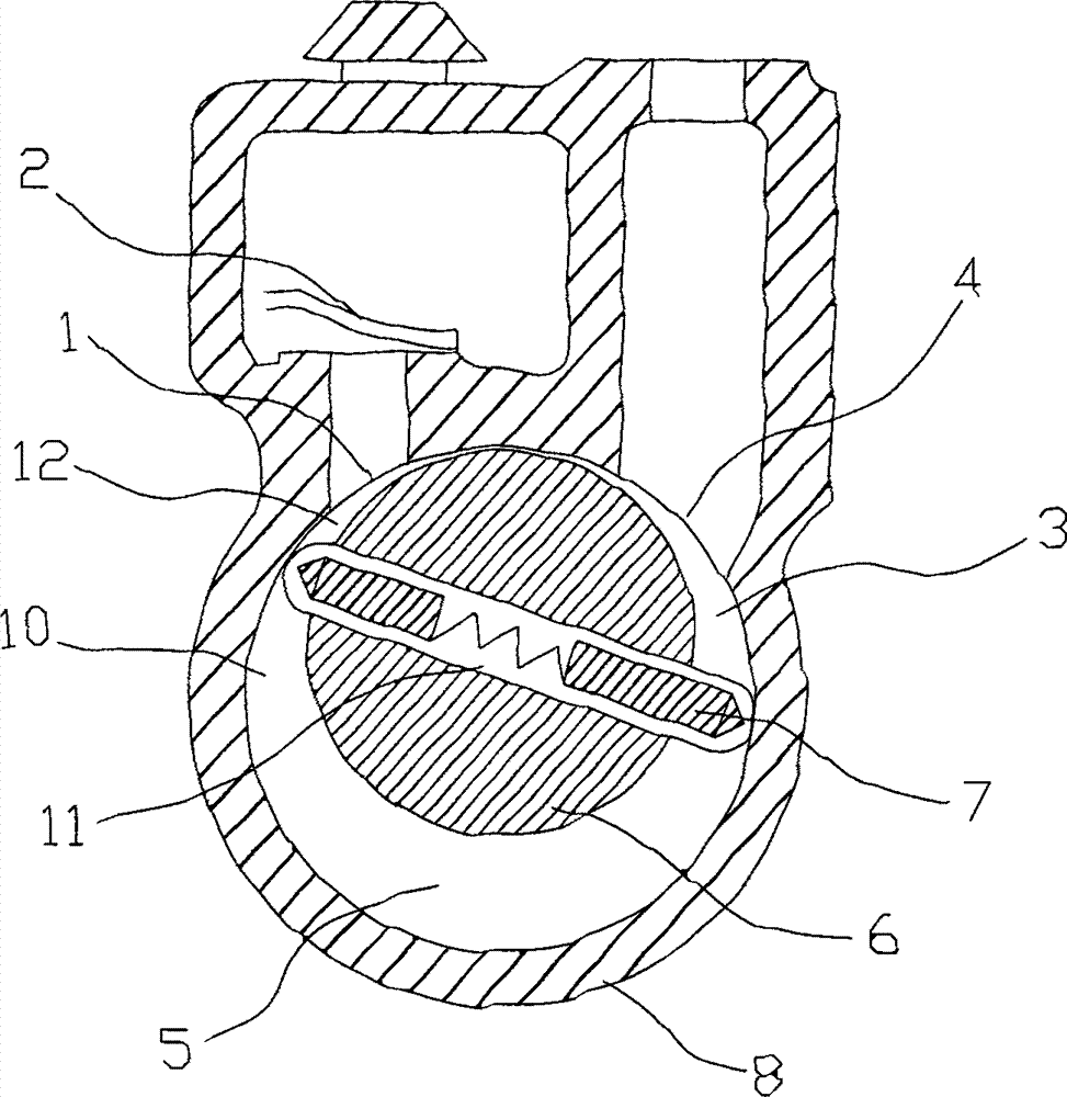
[0009] Such as figure 1 As shown, the present invention provides a rotary vane vacuum pump, which includes a pump body 8 and an eccentric rotor 6. A cylindrical working chamber 10 is arranged in the pump body 8. The eccentric rotor 6 is a cylinder arranged tangentially to the working chamber 10. The eccentric rotor 6 is provided with a rotary vane channel 11, and the telescopic rotary vane 7 is pierced in the stretching rotary vane channel 11. The two ends of the telescopic rotary vane 7 are against the inner wall of the working chamber 10, and the working chamber 10 is also provided with a suction port 4 and an exhaust port. The gas port 1, the eccentric rotor 6 and the tangent to the working chamber 10 are located between the suction port 4 and the exhaust port 1.

[0010] The tangent between the eccentric rotor 6 an...


PUM


Abstract

The invention provides a sliding-vane rotary vacuum pump. The sliding-vane rotary vacuum pump comprises a pump body and an eccentric rotor, wherein a cylindrical working chamber is arranged in the pump body; the eccentric rotor is a cylinder which is tangent to the working chamber; a rotary vane channel is formed in the eccentric rotor; a telescopic rotary vane is perforated in the rotary vane channel; two ends of the telescopic rotary vane prop against the inner wall of the working chamber; an air suction opening and an air exhaust opening are also formed in the working chamber; a tangent part between the eccentric rotor and the working chamber is located between the air suction opening and the air exhaust opening. When the eccentric rotor rotates clockwise, the volume of an air suction cavity near the air suction opening is greatly increased, and the pumping is started; after the pumping is ended, the chamber rotates over the position of the air suction opening and becomes an isolation chamber; when the chamber rotates to the position of the air exhaust opening again, air is exhausted outside the air exhaust opening in the process of gradually decreasing an air exhaust chamber, and the pumping is completed.

Description

technical field [0001] The invention relates to the field of vacuum pumps, in particular to a rotary vane vacuum pump. Background technique [0002] The vacuum pump is a rotary variable volume gas delivery pump. The vacuum pump must be used with a backing pump. It has a large pumping speed in a wide pressure range and is not sensitive to dust and water vapor in the pumped gas. Widely used in metallurgy, chemical industry, food, electronic coating and other industries. Most of the current vacuum pumps adopt intermittent working mode, and cannot realize continuous working mode. Contents of the invention [0003] The object of the present invention is to provide a rotary vane vacuum pump to solve the problem of uneven flow in the above-mentioned prior art problems. [0004] The invention provides a rotary vane vacuum pump, which includes a pump body and an eccentric rotor. A cylindrical working chamber is arranged in the pump body. The eccentric rotor is a cylinder arranged...

Claims


Application Information

Patent Timeline
IPC IPC(8): F04C18/344
Inventor 周汉忠
Owner 周汉忠
Why Eureka
Try Eureka