Air-conditioning refrigeration circulating system and air conditioner

A technology of circulation system and air-conditioning refrigeration, applied in air-conditioning systems, refrigerators, compressors with reversible circulation, etc., can solve the problems of large pressure drop of gaseous refrigerant, increase of energy consumption of refrigeration cycle system, and increase of cycle work capacity, etc. Achieve the effect of increasing cooling capacity, small pressure drop, and small pressure drop loss

CN107763774AInactive Publication Date: 2018-03-06QINGDAO HAIER AIR CONDITIONER GENERAL CORP LTD
6 Cites 7 Cited by

Patent Information

Authority / Receiving Office
CN · China
Patent Type
Applications(China)
Current Assignee / Owner
Publication Date
2018-03-06
Estimated Expiration
Not applicable · inactive patent

Smart Images

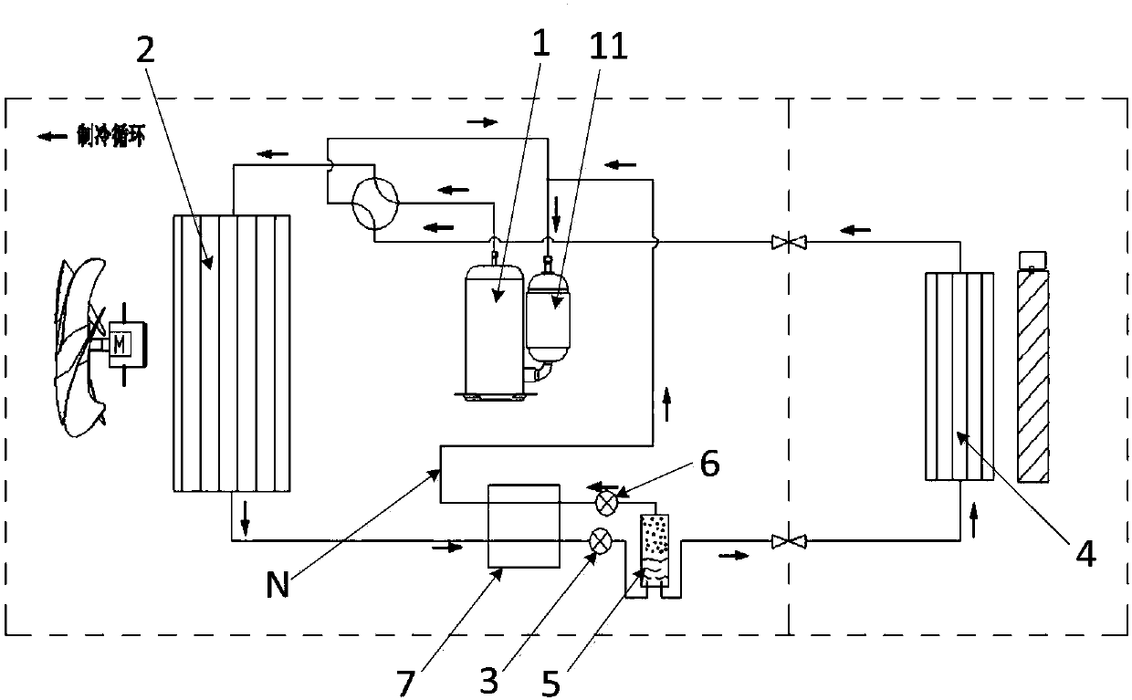
  • Figure 1
    Figure 1
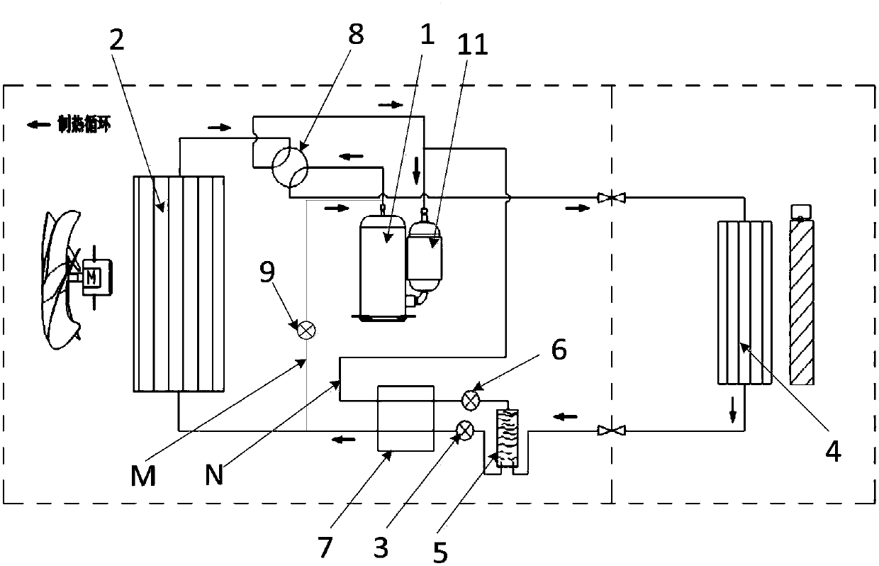
  • Figure 2
    Figure 2
Patent Text Reader

Abstract

The invention belongs to the technical field of air conditioners and particularly relates to an air-conditioning refrigeration circulating system and an air conditioner. In order to improve the air-conditioning refrigeration circulating effect and reduce the energy consumption, the system comprises a compressor in series connection with a main loop, an outdoor heat exchanger, a first throttling device and indoor heat exchanger; a first gas-liquid separator is further in series connection with the main loop; a bypass loop is arranged between the first gas-liquid separator and the compressor; after a cold medium flowing out of the outdoor heat exchanger flows into the first gas-liquid separator through the first throttling device, a gaseous cold medium flows to the compressor along the bypass loop, and a liquid cold medium flows to the indoor heat exchanger along the main loop. By the aid of the system and the air conditioner, the pressure drop loss of the gaseous cold medium in the system is low, the energy consumption of the system is reduced, meanwhile, the return gas pressure of the system can be increased, and the exhaust pressure and the condensing temperature of the system areincreased, so that the heat convection temperature difference of the cold medium in the outdoor heat exchanger is increased, and the purpose of increasing the refrigerating capacity of the system isachieved.
Need to check novelty before this filing date? Find Prior Art

Description

technical field

[0001] The invention belongs to the technical field of air conditioners, and in particular relates to an air conditioner refrigeration cycle system and an air conditioner. Background technique

[0002] The existing air-conditioning refrigeration cycle system usually consists of a condenser, a throttling device, an evaporator, and a compressor to form a refrigeration cycle loop. It flows into a low-temperature and low-pressure liquid, and then enters the evaporator to absorb heat and evaporate to complete the refrigeration cycle.

[0003] Refrigerant flows in the air-conditioning refrigeration cycle system, which has the physical characteristics of latent heat of vaporization and specific heat capacity at equal pressure, and participates in heat exchange with the environment. The cooling capacity per unit mass of a refrigerant is an important performance characteristic, meaning that the more mass a refrigerant has to a certain extent, the better the cooling o...

Examples

Embodiment Construction

[0018] Preferred embodiments of the present invention are described below with reference to the accompanying drawings. Those skilled in the art should understand that these embodiments are only used to explain the technical principles of the present invention, and are not intended to limit the protection scope of the present invention.

[0019] Such as figure 1 As shown, the air-conditioning refrigeration cycle system of the present invention includes a compressor 1 connected in series in the main circuit, an outdoor heat exchanger 2, a first throttling device 3, an indoor heat exchanger 4 and a first gas-liquid separator connected in series on the main circuit 5. Wherein, a bypass circuit N is provided between the first gas-liquid separator 5 and the compressor 1, and the refrigerant flowing out from the outdoor heat exchanger 2 flows into the first gas-liquid separator 5 through the first throttling device 3, and the gaseous refrigerant The liquid refrigerant flows to the ...