Power generation system using heating furnace waste heat integrally

A power generation system and heating furnace technology, which is applied to lighting and heating equipment, furnaces, waste heat treatment, etc., can solve problems such as waste of energy, achieve the effects of improving thermal efficiency, prolonging service life, and improving thermal efficiency of power generation

Active Publication Date: 2014-12-03
HUATIAN ENG & TECH CORP MCC
View PDF5 Cites 18 Cited by
  • Summary
  • Abstract
  • Description
  • Claims
  • Application Information

AI Technical Summary

Problems solved by technology

Under conventional combustion and oxygen-enriched combustion conditions, the flue gas temperature of the heating furnace is about 900°C. The traditional waste heat recovery method is to install a high-efficiency air and gas preheater in the flue, and use the waste heat to preheat the combustion air and gas. After the combustion-supporting air and gas are preheated, the flue gas temperature is still about 350°C, and then it is directly discharged through the chimney, which wastes a lot of energy

Method used


Image

  • Power generation system using heating furnace waste heat integrally
  • Power generation system using heating furnace waste heat integrally

Examples


Embodiment 1

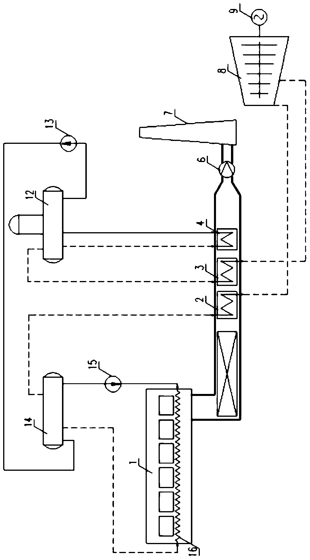
[0016] Such as figure 1 As shown, the waste heat recovered in this embodiment includes two parts: the waste heat of the cooling water beam in the furnace of the heating furnace and the flue gas at about 350° C. in the tail flue of the heating furnace. A steam-water cooling heat exchanger 16 is arranged in the hearth of the heating furnace 1 to absorb the waste heat of the cooling water beam. In the tail flue, a high-pressure superheated steam heat exchanger 2, a low-pressure superheated steam heat exchanger 3, and a low-pressure evaporation tube bundle heat exchanger 4 are arranged in sequence according to the flue gas flow direction, to absorb the waste heat of the flue gas. The end of the tail flue is connected with the induced draft fan 6, and the induced draft fan 6 is connected with the chimney 7. After the high-temperature flue gas generated by combustion in the furnace of the heating furnace preheats the air and gas, the temperature of the flue gas is reduced to about ...

Embodiment 2

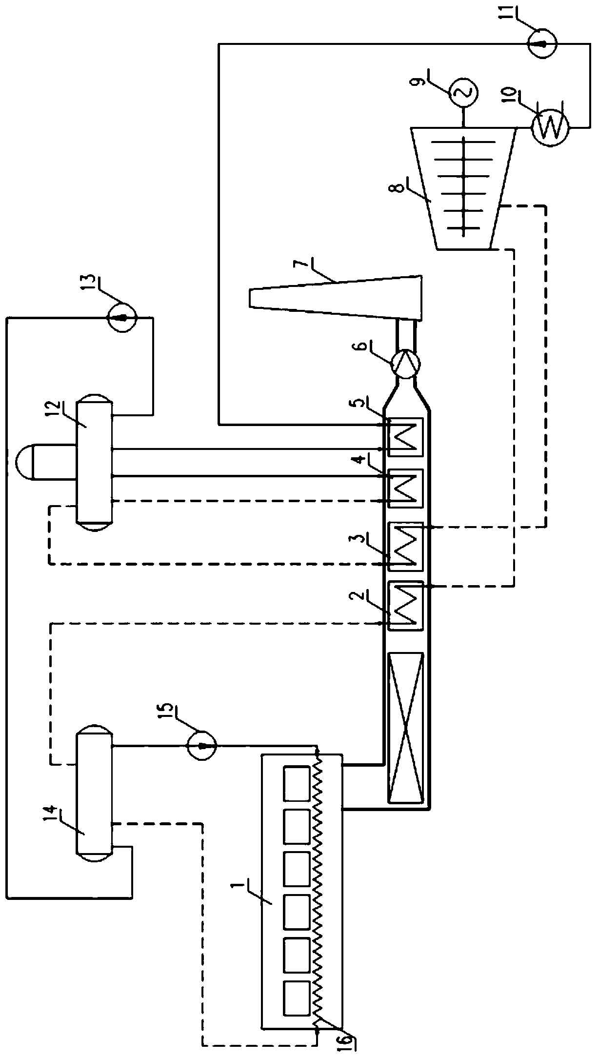
[0029] Such as figure 2 As shown, in this embodiment, on the basis of the above-mentioned embodiment 1, an economizer 5 is arranged in the tail flue, and the economizer is arranged after the low-pressure evaporation tube bundle heat exchanger according to the flow direction of the flue gas. The condenser 10 of the condensing steam turbine 8 is connected to the inlet of the economizer through a condensate pump 11, and the outlet of the economizer is connected to the low-pressure steam drum, and the condensate recovered by the condenser is in the After absorbing heat in the economizer, it enters the low-pressure steam drum 12.

[0030] In this case, the exhaust steam at the tail of the steam-enhancing condensing steam turbine 8 passes through the condenser 10 and becomes condensed water, which is pumped into the economizer 5 by the condensed water pump 11 to absorb the low-temperature waste heat of the flue gas, and the water after absorbing heat enters the In the low-pressure...

Embodiment 3

[0034] The difference between this embodiment and the above-mentioned embodiment 1 is that: the high pressure in the high-pressure saturated steam and the high-pressure superheated steam in this embodiment is 0.8Mpa, and the low pressure in the low-pressure saturated steam and the low-pressure superheated steam is 0.2MPa.


PUM


Abstract

The invention discloses a power generation system using the heating furnace waste heat integrally and aims to generate power by integrally using the cooling water beam waste heat in a heating furnace and the waste heat of smoke in a tail smoke channel. The system at least comprises a high-pressure superheated steam producing mechanism, a low-pressure superheated steam producing mechanism, a steam supplementing and condensing turbine and a generator. The steam outlet of the high-pressure superheated steam producing mechanism is connected to the main steam port of the steam supplementing and condensing turbine, and the steam outlet of the low-pressure superheated steam producing mechanism is connected to the steam supplementing port of the steam supplementing and condensing turbine. The produced high-pressure superheated steam and the low-pressure superheated steam enter the main steam port and the steam supplementing port to generate power respectively, energy is utilized in a stepped manner, and the power generating efficiency is improved; by the aid of the system, the smoke waste heat is recovered as much as possible, the temperature of the smoke during exhausting is decreased, and the waste heat source loss is reduced; since the hot steam is adopted for power generation, the quality of power generated by the steam is improved, the power generating efficiency is improved, and the service life of the steam supplementing and condensing turbine is prolonged.

Description

technical field [0001] The invention relates to a power generation system for comprehensive utilization of residual heat of a heating furnace. Background technique [0002] At present, the heating furnace of the metallurgical plant adopts regenerative combustion, conventional combustion and oxygen-enriched combustion. For conventional combustion, since there is 79% nitrogen in the air in addition to 21% oxygen, nitrogen does not participate in the combustion reaction during the combustion process, and all of it is converted into flue gas. Oxygen-enriched combustion uses pure oxygen to partially replace combustion-supporting air and fuel for combustion reactions. The use of oxygen-enriched combustion can reduce the amount of flue gas and reduce the heat taken away by the flue gas. Under conventional combustion and oxygen-enriched combustion conditions, the flue gas temperature of the heating furnace is about 900°C. The traditional waste heat recovery method is to install a h...

Claims


Application Information

Patent Timeline
Patent Type & Authority Applications(China)
IPC IPC(8): F27D17/00F01D15/10
CPCY02P10/25Y02P80/15
Inventor 王雷
Owner HUATIAN ENG & TECH CORP MCC
Why Eureka
Try Eureka