
Labyrinth type minimum flow valve

A minimum flow, labyrinth technology, applied in the valve's device for absorbing fluid energy, lift valve, valve details, etc., can solve the problems of flashing and cavitation, high valve pressure difference, and it is not easy to achieve zero leakage. The effect of reducing erosion damage and prolonging service life

Inactive Publication Date: 2014-06-18
SUZHOU DOUSON VALVE CO LTD
View PDF13 Cites 4 Cited by
  • Summary
  • Abstract
  • Description
  • Claims
  • Application Information

AI Technical Summary

Problems solved by technology

However, due to the high pressure difference of the valve and the small thrust of the actuator of the regulating valve, it is generally not easy to achieve zero leakage when the valve is closed. It is inevitable that flashing and cavitation will occur when the high-pressure reducing valve is used in this working condition

Method used


Image

  • Labyrinth type minimum flow valve
  • Labyrinth type minimum flow valve

Examples


Embodiment Construction

[0015] The preferred embodiments of the present invention will be described in detail below in conjunction with the accompanying drawings, so that the advantages and features of the present invention can be more easily understood by those skilled in the art, so as to define the protection scope of the present invention more clearly.

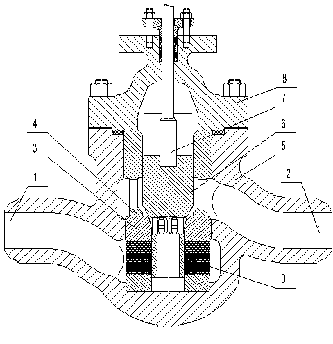
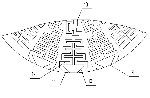
[0016] see figure 1 with figure 2 , the embodiment of the present invention includes: a labyrinth minimum flow valve, including: a valve body 5, a valve cover 8, a valve stem 7, the valve cover 8 is installed above the valve body 5, and one side below the valve body 5 The water inlet flow channel 2 is set, the water outlet flow channel 1 is set on the other side below the valve body 5, and the valve seat 3 is arranged at the intersection of the water inlet flow channel 2 and the water outlet flow channel 1, and the periphery of the valve seat 3 is evenly welded. A labyrinth disc 9, the labyrinth disc 9 is arranged downstream of the water inlet ...


PUM


Abstract

The invention discloses a labyrinth type minimum flow valve which comprises a valve body, a valve cover and a valve rod. The valve cover is installed above the valve body. A water inlet passageway is arranged on one side of the position below the valve body. A water outlet passageway is arranged on the other side of the position below the valve body. The passageway intersection of the water inlet passageway and the water outlet passageway is provided with a valve base. A plurality of labyrinth discs are evenly welded to the periphery of the valve base and arranged at the downstream portion of the water inlet passageway. One end of the valve rod is fixed into the valve cover. The other end of the valve rod is provided with a valve element which is movably arranged into the inner wall of the valve base. Through the method, the labyrinth type minimum flow valve can be effectively sealed and can effectively prevent cavitation.

Description

technical field [0001] The invention relates to a labyrinth-type minimum flow valve, in particular to a key valve used in power plant boiler feed water systems for protection of feed water pumps. Background technique [0002] In the prior art, the minimum flow valve of the feedwater pump is also called the recirculation valve of the feedwater pump. The minimum flow valve of the feedwater recirculation is used to bypass the feedwater pump of the large-capacity power plant boiler supporting the subcritical thermal power generation unit, and it is required to be able to throttle more effectively. Reduce the speed, reduce or eliminate the impact of cavitation on valves and pipelines, make the valve more reliable to maintain zero leakage when it is closed, and maintain a longer service life. However, due to the high pressure difference of the valve and the small thrust of the actuator of the regulating valve, it is generally not easy to achieve zero leakage when the valve is clos...

Claims


Application Information

Patent Timeline
Patent Type & Authority Applications(China)
IPC IPC(8): F16K1/00F16K1/52
CPCF16K1/52F16K47/04
Inventor 邹利明石明张国明刘建同
Owner SUZHOU DOUSON VALVE CO LTD
Learn More