
Thermal mixing heat network heater

The utility model relates to a heating network heater and a heat-mixing technology, which is applied to heating the heating network. , In the field of hot-mixed heat network heaters, it can solve the problems of low heat transfer efficiency, small pressure loss and large pressure loss of heat network heaters, and achieve the effects of reasonable and compact structure, reduced effective heat exchange area and low resistance loss.

Active Publication Date: 2016-05-18
四平市巨元瀚洋板式换热器有限公司
View PDF3 Cites 2 Cited by
  • Summary
  • Abstract
  • Description
  • Claims
  • Application Information

AI Technical Summary

Problems solved by technology

[0002] At present, it is widely used in thermal power plants, and the heat exchange tubes of steam-water or water-water heating network heaters in urban central heating systems all use a single light tube or a single characteristic tube to improve heat transfer. The shortcomings of the heat network heater are obvious, which are manifested in: ①. The heat transfer efficiency of the bare tube heat network heater is low, the pressure loss is small (the allowable pressure loss cannot be fully utilized), and the heat exchange area required for the same working condition is large, accounting for The ground space is relatively large; ②, the heat transfer efficiency of the characteristic tube heating network heater is high, but the pressure loss is too large

Method used


Image

  • Thermal mixing heat network heater
  • Thermal mixing heat network heater
  • Thermal mixing heat network heater

Examples


Embodiment Construction

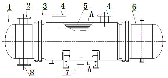
[0016] Such as figure 1 As shown: the heat network heater includes a left tube box 1 and a right tube box 6, and the tube sheet shell welding 3 arranged in the middle of the left tube box 1 and the right tube box 6 is arranged inside the tube sheet shell welding 3 The tube bundle 5.

[0017] The left tube box 1 is provided with an inlet 8 of secondary network circulating water and an outlet 2 of secondary network circulating water, and the tube plate shell welding 3 is provided with a steam inlet 4 and a steam outlet 7 .

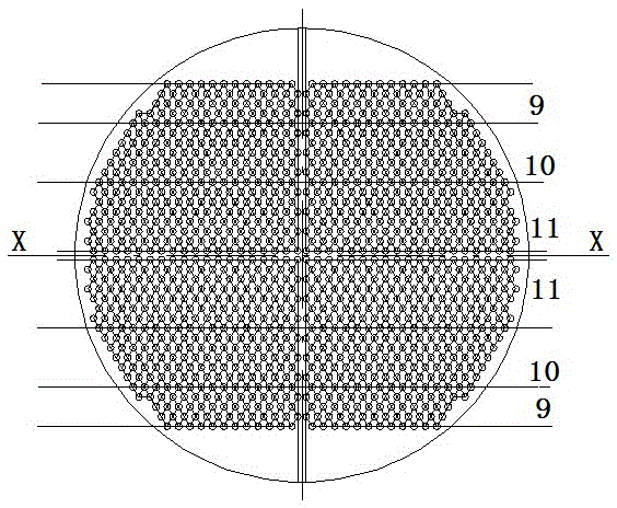
[0018] Such as figure 2 As shown: the tube bundle 5 is divided into three areas, namely the low resistance area 9 close to the upper and lower ends of the shell, the high resistance area 11 close to the center line of the tube bundle, and the high resistance area set between the high resistance area and the low resistance area. In the transition zone 10, the three zones are symmetrically arranged up and down relative to the horizontal centerline X-axis. ...


PUM


Abstract

The invention belongs to the field of manufacture of heat exchange devices, and particularly relates to a heat mixing heater for a heating network. The heater is particularly suitable for heating various large steam-water and water-water heat transfer heating networks. The heater for the heating network comprises a left tube box, a right tube box, a tube plate shell seam and a tube bundle, the tube plate shell seam is arranged between the left tube box and the right tube box, and the tube bundle is arranged inside the tube plate shell seam. The heater is characterized in that the tube bundle is divided into three areas including a low-resistance area, a high-resistance area and a transition area, the low-resistance area is close to the upper end and the lower end of a shell, the high-resistance area is close to a tube bundle center line, the transition area is arranged between the high-resistance area and the low-resistance area, and the three areas are vertically and symmetrically are arranged relative to an X axis of the horizontal center line. Heat exchange efficiency is high, pressure loss does not exceed a standard, and the best point for balancing pressure drop and efficiency is achieved.

Description

technical field [0001] The invention belongs to the field of heat exchange equipment manufacturing, and specifically relates to a heat-mixing heat network heater, which is especially suitable for heating various large-scale steam-water and water-water heat transfer heat networks. Background technique [0002] At present, it is widely used in thermal power plants, and the heat exchange tubes of steam-water or water-water heating network heaters in urban central heating systems all use a single light tube or a single characteristic tube to improve heat transfer. The shortcomings of the heat network heater are obvious, which are manifested in: ①. The heat transfer efficiency of the bare tube heat network heater is low, the pressure loss is small (the allowable pressure loss cannot be fully utilized), and the heat exchange area required for the same working condition is large, accounting for The ground space is relatively large; ②, the characteristic tube heating network heater ...

Claims


Application Information

Patent Timeline
Patent Type & Authority Patents(China)
IPC IPC(8): F28D7/16F28D9/00
Inventor 姜宇詹福才姜享成李健郭建勋张赫
Owner 四平市巨元瀚洋板式换热器有限公司
Learn More