Anti-GPS interference test system

A technology of jamming test and jammer, applied in the field of anti-GPS jamming system, can solve the problem of low accuracy of anti-GPS jamming test, and achieve the effect of strong anti-GPS jamming ability and high test accuracy

Inactive Publication Date: 2014-06-18
吕涛
View PDF2 Cites 0 Cited by
  • Summary
  • Abstract
  • Description
  • Claims
  • Application Information

AI Technical Summary

Problems solved by technology

[0003] The present invention aims to solve the problem of low test accuracy of the c

Method used


Image

  • Anti-GPS interference test system
  • Anti-GPS interference test system
  • Anti-GPS interference test system

Examples


specific Embodiment approach 1

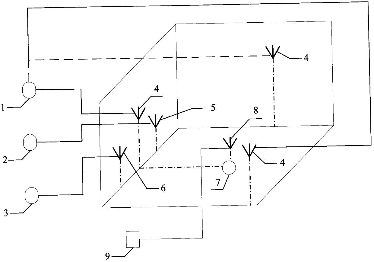
[0015] Specific implementation mode 1. Combination figure 1 Describe this specific embodiment, the anti-GPS interference test system, which includes No. 1 jammer 1, No. 2 jammer 2, No. 3 jammer 3, No. 1 antenna 4, No. 2 antenna 5, No. 3 antenna 6, adaptive withering Antenna 7 and spectrum analyzer 8;

[0016] The first antenna 4 is used to receive the interference signal output by the first jammer 1; the second antenna 5 is used to receive the interference signal output by the second jammer 2; the third antenna 6 is used to receive the interference signal output by the third jammer 3 ;

[0017] The end of the adaptive decay antenna 7 is connected to the No. 1 input of the spectrum analyzer 7; the end of the No. 1 antenna 4 is connected to the No. 2 input of the spectrum analyzer 7;

[0018] The adaptive withering antenna 7 is set in the center of the test area, and the No. 2 antenna 5 and the No. 3 antenna 6 are both arranged on one side of the adaptive withering antenna 7, ...

specific Embodiment approach 2

[0020] Embodiment 2. The difference between this embodiment and the anti-GPS interference testing system described in Embodiment 1 is that it also includes an adaptive withered antenna working condition detection device 9, and the adaptive withered antenna working condition detection device 9 Used to receive signals transmitted by the adaptive withering antenna 7 .

specific Embodiment approach 3

[0021] Embodiment 3. The difference between this embodiment and the anti-GPS interference test system described in Embodiment 1 is that the azimuth angle of the second antenna 5 is -10°, and the pitch is 0°.


PUM


Abstract

The invention relates to an anti-GPS interference system, and discloses an anti-GPS interference test system, for solving the problem of low test precision of a conventional anti-GPS interference test. In the system, a first antenna is used for receiving an interference signal output by a first jammer; a second antenna is used for receiving an interference signal output by a second jammer; a third antenna is used for receiving an interference signal output by a third jammer; the tail end of a self-adaptive zeroing antenna is connected with the first input end of a frequency spectrum analyzer; the tail end of the first antenna is connected with the second input end of the frequency spectrum analyzer; the self-adaptive zeroing antenna is arranged at the center of a test area; the second antenna and the third antenna are both arranged at one side of the self-adaptive zeroing antenna and are each taken as a low-elevation angle interference device; and the first antenna is arranged in the test area and is taken as an interference test device. The anti-GPS interference test system is applied to an anti-GPS interference test.

Description

technical field [0001] The invention relates to an anti-GPS interference system. Background technique [0002] At present, in the anti-GPS interference test, no matter in the single-interference environment or the three-interference environment, the test anti-GPS interference ability is poor, and the test accuracy is low. Contents of the invention [0003] The invention aims to solve the problem of low test accuracy of the current anti-GPS interference test, thereby providing an anti-GPS interference system. [0004] Anti-GPS jamming test system, which includes No. 1 jammer 1, No. 2 jammer 2, No. 3 jammer 3, No. 1 antenna 4, No. 2 antenna 5, No. 3 antenna 6, adaptive withering antenna 7 and spectrum analyzer 8; [0005] The first antenna 4 is used to receive the interference signal output by the first jammer 1; the second antenna 5 is used to receive the interference signal output by the second jammer 2; the third antenna 6 is used to receive the interference signal out...

Claims


Application Information

Patent Timeline
IPC IPC(8): G01S19/21
CPCG01S19/21
Inventor 吕涛李强张笑瀛王怀军冯三任崔伟峰梁靖宇徐锐
Owner 吕涛
Why Eureka
Try Eureka