Induction motor rotor flux linkage control method and control circuit and induction motor

A technology of induction motor and rotor flux linkage, which is used in motor generator control, electronic commutation motor control, and electromechanical brake control. The effect of improving low-speed control accuracy and improving observation accuracy

Active Publication Date: 2016-08-31
CHINA CNR CORPORATION
View PDF3 Cites 0 Cited by
  • Summary
  • Abstract
  • Description
  • Claims
  • Application Information

AI Technical Summary

Problems solved by technology

However, the voltage model method is affected by the deviation of the stator resistance, and the accuracy in the low speed area is low
In addition, due to the introduction of a first-order low-pass filter in the voltage model, there will be errors in the magnitude and phase of the flux linkage, especially at low speeds, and even failure

Method used


Image

  • Induction motor rotor flux linkage control method and control circuit and induction motor
  • Induction motor rotor flux linkage control method and control circuit and induction motor
  • Induction motor rotor flux linkage control method and control circuit and induction motor

Examples


Embodiment Construction

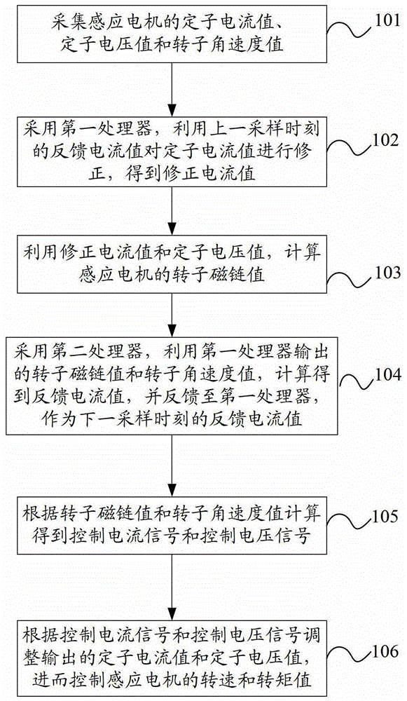
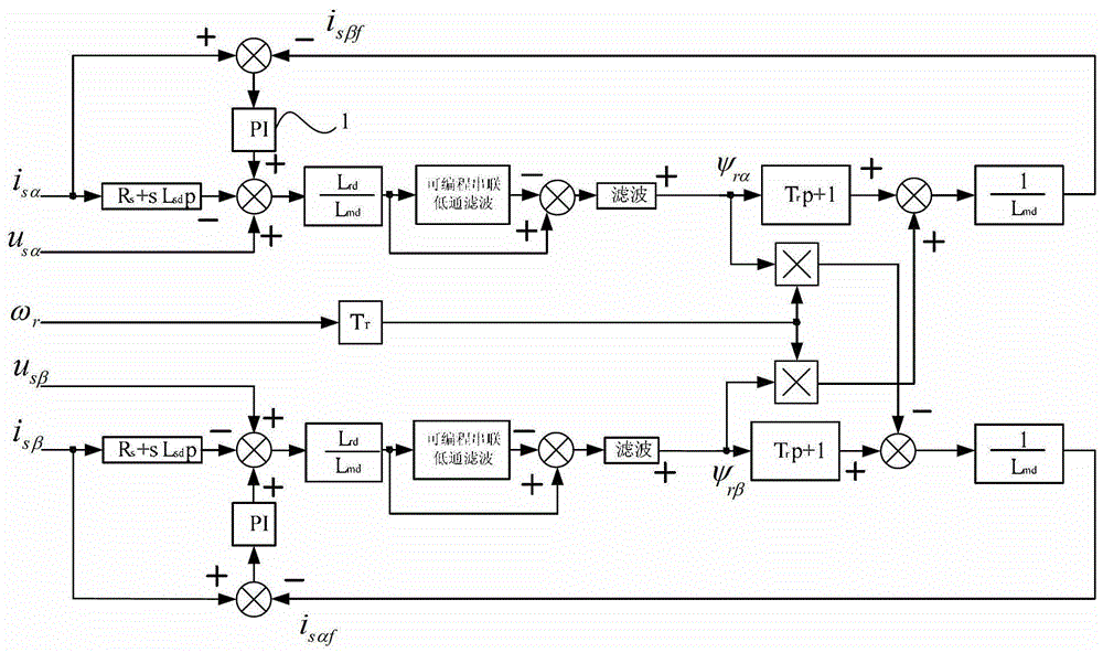
[0025] figure 1 The flow chart of the method for controlling the flux linkage of the induction motor rotor provided by the embodiment of the present invention, figure 2 A schematic diagram of a method for controlling flux linkage of an induction motor rotor provided by an embodiment of the present invention. combine figure 1 and figure 2 , the induction motor rotor flux control method provided in this embodiment includes:

[0026] Step 101, collect the stator current value, stator voltage value and rotor angular velocity value of the induction motor.

[0027] Specifically, sensors are used to collect the stator current value, fixed value voltage value and rotor angular velocity value of the induction motor.

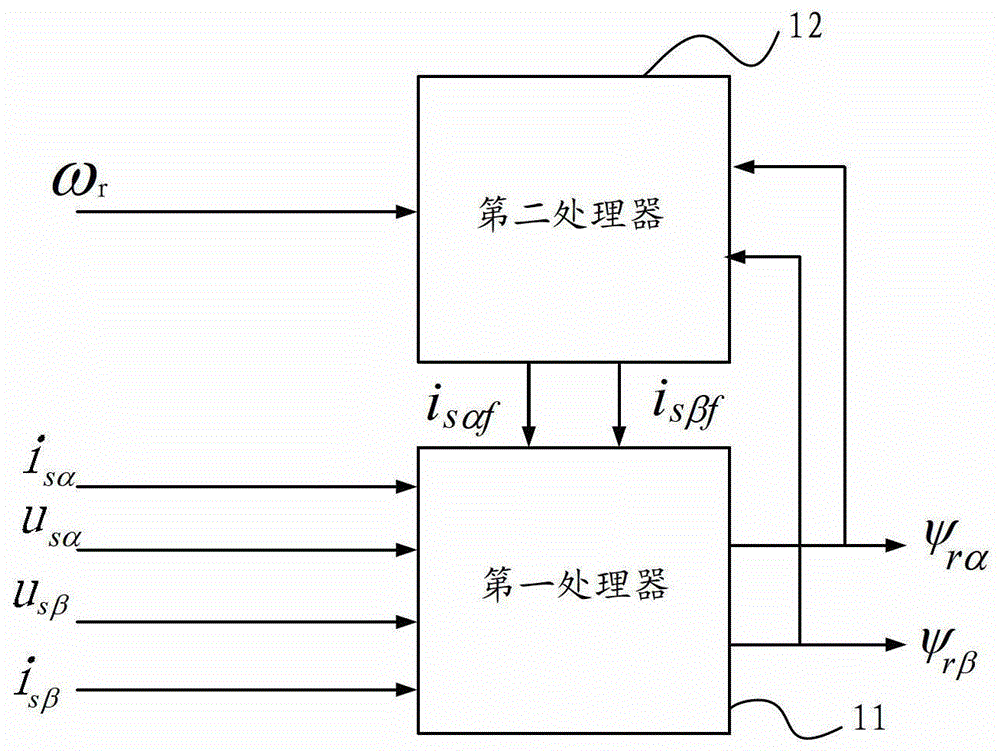
[0028] Step 102, using the first processor to correct the stator current value by using the feedback current value at the last sampling moment to obtain the corrected current value.

[0029] Specifically, the feedback current value at the last sampling moment is ca...


PUM


Abstract

The invention provides an induction motor rotor magnetic link control method, an induction motor rotor magnetic link control circuit and an induction motor. The method comprises the following steps of acquiring a stator current value, a stator voltage value and a rotor angular speed value of the induction motor; calculating a rotor magnetic link value of the induction motor by using a first processor; calculating a feedback current value by using a second processor, and feeding the feedback current value as the feedback current value at the next sampling time back to the first processor; according to the rotor magnetic link value, calculating a control current signal and a control voltage signal, thus adjusting the output stator current value and stator voltage value. According to the induction motor rotor magnetic link control method provided by the invention, the feedback current value is calculated by using the second processor and is fed back to the first processor to participate in the calculation of the first processor, and the induction motor rotor magnetic link value at the next sampling time is output, so that the rotation speed and the torque value of the induction motor at the next sampling time is adjusted, the observation precision of a rotor magnetic link obtained when the induction motor is low in speed is improved, and the low-speed control precision of the induction motor is improved.

Description

technical field [0001] The invention relates to a motor control technology, in particular to a method for controlling flux linkage of an induction motor rotor, a control circuit and an induction motor. Background technique [0002] High-performance AC speed control is widely used in transportation and other fields, among which vector control is the most widely used control method for high-performance control of induction motors. In the vector control, the vector control based on the rotor field orientation can realize the decoupling control of the induction motor, and its control performance is comparable to that of the DC motor. In the induction motor vector control system, the flux linkage observation is the key link to realize the accurate orientation of the magnetic field, which directly affects the performance of the control system. [0003] In practical applications, the indirect observation method is usually used to detect physical quantities such as the stator volta...

Claims


Application Information

Patent Timeline
Patent Type & Authority Patents(China)
IPC IPC(8): H02P21/06
Inventor 丛培城李婷婷赵研
Owner CHINA CNR CORPORATION
Why Eureka
Try Eureka