Automatic bias voltage control system and method for light IQ modulator

A technology of IQ modulator and automatic bias, which is applied in phase modulation carrier system, transmission system, electromagnetic wave transmission system, etc. It can solve the problems of system performance loss, device noise bias not controlled at the optimal point, etc., and achieve the reduction loss, simple structure, and precise control of bias voltage effects

Inactive Publication Date: 2014-06-18
WUHAN POST & TELECOMM RES INST CO LTD
View PDF6 Cites 38 Cited by
  • Summary
  • Abstract
  • Description
  • Claims
  • Application Information

AI Technical Summary

Problems solved by technology

However, in actual research, it is found that although these methods are theoretically feasible, since the optical signal power does not change significantly in the re...

Method used


Image

  • Automatic bias voltage control system and method for light IQ modulator
  • Automatic bias voltage control system and method for light IQ modulator
  • Automatic bias voltage control system and method for light IQ modulator

Examples


Embodiment Construction

[0022] The present invention will be described in further detail below in conjunction with the accompanying drawings.

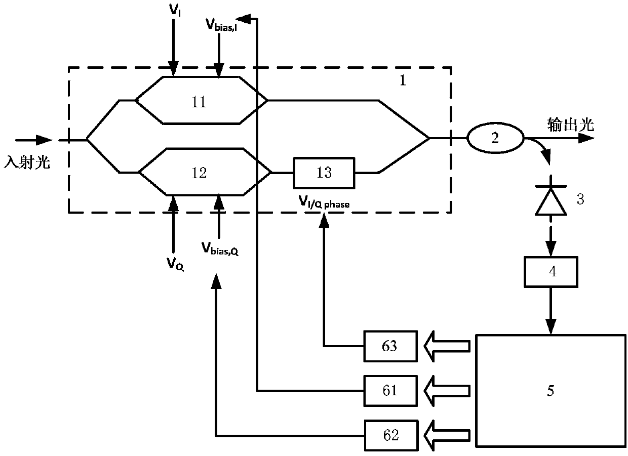
[0023] like figure 1 As shown, the optical IQ modulator automatic bias control system of the present invention includes an optical IQ modulator 1, a coupler 2, a photodetector (PD, Photo-detector) 3 and a digital signal processor 5, and two parts of the IQ modulator 1 The arms are respectively provided with an I-way MZM modulator 11 and a Q-way MZM modulator 12, the Q-way MZM modulator 12 is also connected to an optical phase shifter 13, and the output of the IQ modulator 1 is connected to a coupler 2, and the coupler 2 is coupled to the I-way output of the MZM modulator 11 and the optical phase shifter 13, and output an optical signal. The photodetector 3 detects part of the energy of the output optical signal and converts it into an electrical signal, and after being sampled by the analog-to-digital converter 4, it is sent to the digital signal processor 5...


PUM


Abstract

The invention discloses an automatic bias voltage control system for a light IQ modulator, and relates to the field of light signal modulation in a light communication system. The automatic bias voltage control system comprises the light IQ modulator, a coupler, a photoelectric detector and a digital signal processor, wherein the photoelectric detector is used for detecting partial energy of a light signal and converting the partial energy into an electric signal; after being sampled through an analog-digital converter, the electric signal is input into the digital signal processor; the digital signal processor adjusts I-path bias voltage, Q-path bias voltage and orthogonal bias voltage of a light phase shifter respectively through three digital-analog converters. The control method comprises the steps of performing rough adjustment on the I-path bias voltage and the Q-path bias voltage, applying a shaking signal on two arms I and Q, then obtaining second-order harmonic signal corresponding power with double of a shaking signal frequency, and further obtaining first-order harmonic signal corresponding power with the shaking signal frequency. According to the control system and the control method, the bias voltage is controlled at the optimal point, so that a signal output by the IQ modulator is nearly undistorted, and loss of the system performance is reduced.

Description

technical field [0001] The invention relates to the field of optical signal modulation in an optical communication system, in particular to an automatic bias voltage control system and method for an optical IQ modulator. Background technique [0002] In an optical communication system, an optical IQ modulator based on an MZM (Mach-Zehnder Modulator, Mach-Zehnder) modulator is usually required for high-order modulated optical signals. However, conditions such as temperature will affect the stability of the optical IQ modulator, resulting in a shift in its quiescent operating point, deteriorating system performance. In order to ensure that the signal quality does not affect the system performance, it is necessary to monitor and control the DC bias voltage so that the optical IQ modulator works at the best static operating point. In addition, in order to ensure the mutual orthogonality of the IQ two-way signals, it is also necessary to modulate the bias voltage of the optical ...

Claims


Application Information

Patent Timeline
IPC IPC(8): H04B10/516H04L27/20
CPCG02F1/0123H04B10/50H04B10/50575H04B10/5561
Inventor 黎偲杨奇张旭王元祥孟令恒
Owner WUHAN POST & TELECOMM RES INST CO LTD
Why Eureka
Try Eureka