Horizontal slurry mixing device

A stirring device and slurry technology, applied in mixers, dissolving, mixers and other directions with rotating stirring devices, can solve problems such as large impact force, uneven slurry, and unfavorable service life of blades

Inactive Publication Date: 2016-03-30
JIANGSU ANSHENG TECH
View PDF5 Cites 0 Cited by
  • Summary
  • Abstract
  • Description
  • Claims
  • Application Information

AI Technical Summary

Problems solved by technology

[0002] In the prior art, two adjacent paddles of the horizontal slurry stirring device are usually arranged at intervals, and the paddles only stir the slurry poured into the slurry box. When the amount of slurry poured in is relatively large, the paddles During the mixing process, the impact force of the paddle is relatively large, which is not conducive to the service life of the paddle, and the stirred slurry will also be uneven

Method used


Image

  • Horizontal slurry mixing device
  • Horizontal slurry mixing device

Examples


Embodiment Construction

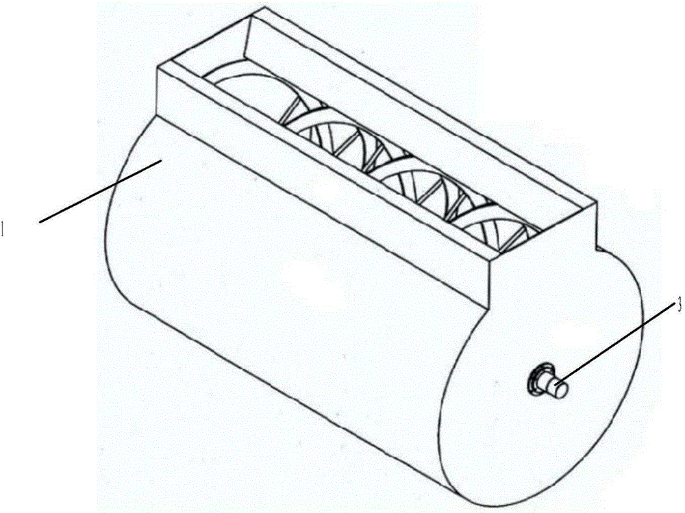
[0010] Such as figure 1 and figure 2 As shown, the horizontal slurry stirring device includes a cylindrical slurry box 1 and a stirring mechanism accommodated in the slurry box 1 .

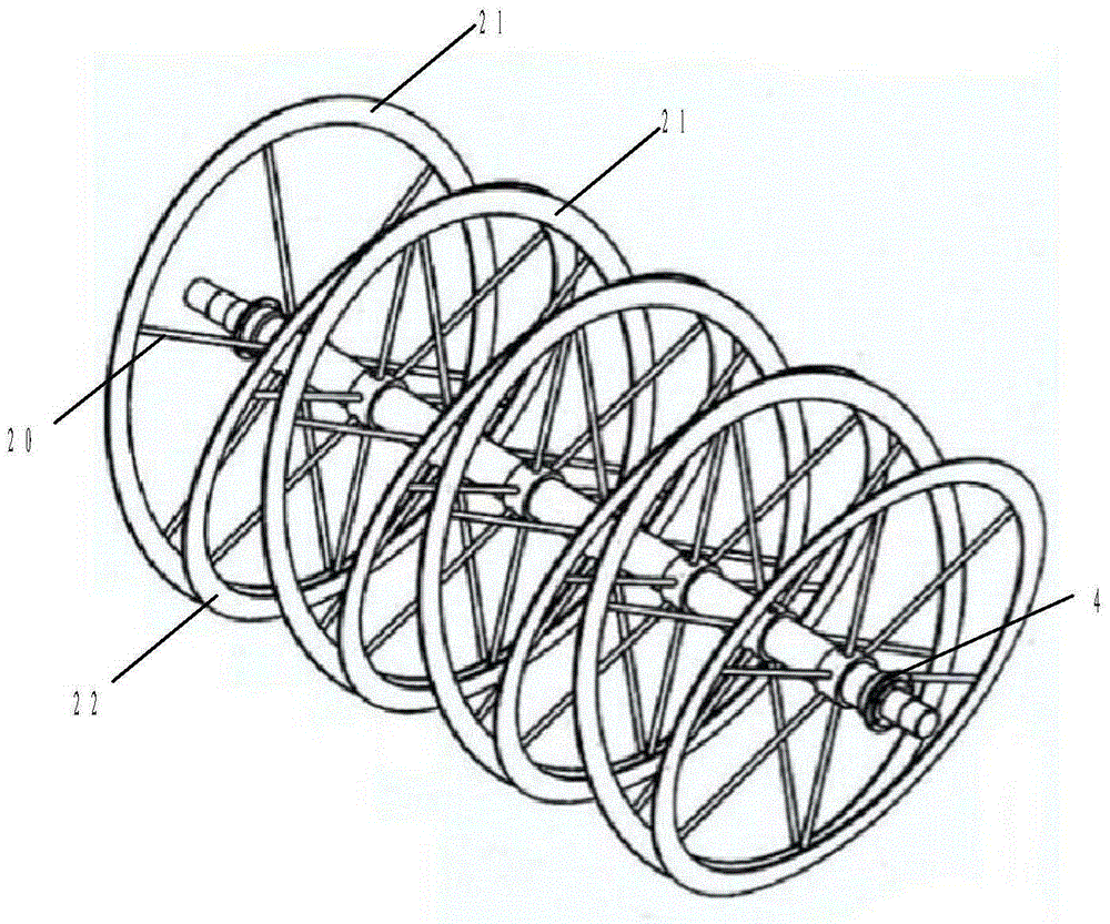
[0011] The stirring mechanism has paddles 2 and a power shaft 3 mounted on the slurry tank 1 , the paddles 2 are equidistantly mounted on the power shaft 3 and rotate together with the rotation of the power shaft 3 . The blade 2 is an oval frame with six spokes 20 in the frame. The blades 2 include first blades 21 and second blades 22 arranged at intervals, and the first blades 21 and the second blades 22 are identical. A second paddle 22 is connected between two adjacent first paddles 21 , and the plane of the first paddle 21 is inclined to the plane of the adjacent second paddle 22 and connected in a V shape.

[0012] The spokes 20 are rod-shaped, and the included angles between two adjacent spokes 20 are equal. The spokes 20 are set in a rod shape, which can reduce the resistance of the sp...


PUM


Abstract

The invention discloses a horizontal-type slurry stirring device for stirring slurry. The horizontal-type slurry stirring device comprises a cylindrical slurry box and a stirring mechanism which is stored in the cylindrical slurry box, wherein the stirring mechanism comprises a stirring power shaft which is supported on two ends of the cylindrical slurry box and elliptic vanes which are fixed on the stirring power shaft through spokes at equal intervals in identical dip angle, every two adjacent vanes are connected with each other to form a V shape, each elliptic vane is obliquely arranged on the power shaft, and the outer edge of each vane is concentric with the stirring power shaft and also concentric with the cylindrical slurry box. When the horizontal-type slurry stirring device is in work, the elliptic vanes are driven by the stirring power shaft to rotate, and the slurry can be turbulent along the sharp variation of the intervals of the vanes because every two adjacent vanes are arranged in the V shape, so that the slurry can be high-efficiently and uniformly dispersed.

Description

technical field [0001] The invention relates to a horizontal slurry stirring device, in particular to a stirring mechanism of the horizontal slurry stirring device. Background technique [0002] In the prior art, two adjacent paddles of the horizontal slurry stirring device are usually arranged at intervals, and the paddles only stir the slurry poured into the slurry box. When the amount of slurry poured in is relatively large, the paddles During the stirring process, the impact force of the paddle is relatively large, which is not conducive to the service life of the paddle, and the stirred slurry will also be uneven. [0003] Therefore, a new technical solution is needed to solve the above problems. Contents of the invention [0004] Purpose of the invention: to provide a new horizontal slurry stirring device, which is beneficial to the uniform stirring of the slurry. [0005] Technical solution 1: a horizontal slurry stirring device for slurry stirring, the horizontal...

Claims


Application Information

Patent Timeline
Patent Type & Authority Patents(China)
IPC IPC(8): B01F7/04
Inventor 高志海
Owner JIANGSU ANSHENG TECH
Why Eureka
Try Eureka