Al technical title is built by PatSnap Al team. It summarizes the technical point description of the patent document.
A mold clamping device and internal circulation technology, which is applied in the field of two-platen direct pressure internal circulation mold clamping device, can solve problems such as limited structural size ratio, uneven force, long structural size, etc., so as to avoid hidden dangers of fracture and improve The effect of short pressing time and uniform force
Inactive Publication Date: 2017-01-04
BEIJING INSTITUTE OF TECHNOLOGYGY
View PDF6 Cites 0 Cited by
Summary
Abstract
Description
Claims
Application Information
AI Technical Summary
This helps you quickly interpret patents by identifying the three key elements:
Problems solved by technology
Method used
Benefits of technology
Problems solved by technology
[0007] Aiming at the problems of long structural size, uneven force, and limited structural size ratio of the existing mold clamping device, the purpose of the present invention is to provide a simple and reasonable structure, high strength and rigidity, uniform force, stable and reliable use, and a wide range of advantages. An Adaptive Isovolume Displacement Internal Circulation Clamping Device
Method used
Image
Click on the blue label to locate the original text in one second.
Reading with bidirectional positioning of images and text.
Examples
Embodiment 1
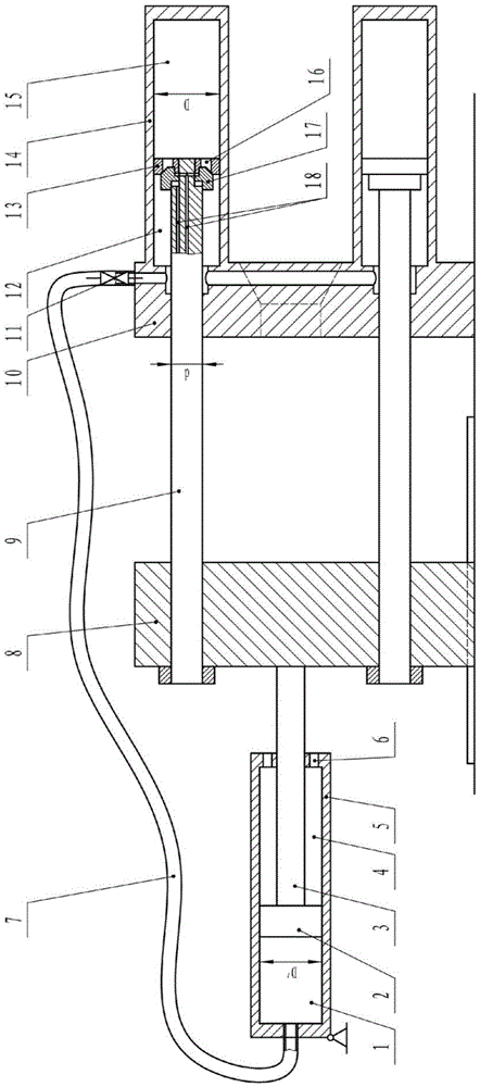
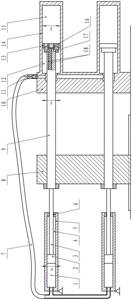
[0027]The use process of Embodiment 1 and Embodiment 2 is: when the mold is closed, the opening and closing valve 17 and the stop valve 11 are driven to open, the rodless chamber 15 and the rod chamber 12 communicate through the through hole 16, and the rod chamber 12 and the supplementary oil chamber 1 is connected through the pipeline 7, and the mold transfer cylinder drives the movable platen 8 to move towards the fixed platen 10, and at the same time, the piston 13, piston rod 9, supplementary piston 2 and supplementary piston rod 3 follow up, and the hydraulic oil passes through the opened through hole 16 from the non-rod Cavity 15 is "equal-volume replacement internal circulation" to the rod cavity 12 and supplementary oil cavity 1; when the mold is locked, the opening and closing valve 17 and the stop valve 11 are driven to close, and the hydraulic oil enters the closed rod cavity 12, and the clamping cylinder The action realizes high-pressure mold clamping through hydra...
PUM
Abstract
The invention relates to the technical field of mold closing devices and provides a supplementary positive-displacement-type isometric displacement internal-circulation mold clamping device with wide using adaptability. The supplementary positive-displacement-type isometric displacement internal-circulation mold clamping device is composed of a movable mold plate, a fixed mold plate, a mold locking oil cylinders and supplementary oil cylinders, wherein each mold clamping oil cylinder comprises a cylinder body, a piston, a piston rod and a switching valve, each supplementary oil cylinder comprises a supplementary cylinder body, a supplementary piston, a supplementary piston rod and a stop valve, each piston separates each cylinder body into a rod cavity and a rodless cavity, each supplementary piston separates each supplementary cylinder body into a supplementary oil cavity and an air cavity, the supplementary oil cavities are connected with the rod cavities, and the stop valves are arranged at the connecting parts of the supplementary oil cavities and the rod cavities. The supplementary positive-displacement-type isometric displacement internal-circulation mold clamping device can achieve 'real isometric displacement internal circulation', that is, hydraulic oil is not required to be drained back to an oil tank during mold closing and oil suction from the oil tank is not required during mold opening, and the supplementary positive-displacement-type isometric displacement internal-circulation mold clamping device has the advantages of low energy consumption, short pressure rising time, good energy-saving and high-efficiency effect, same mold locking oil cylinder structure, simultaneity in action, high mold opening, closing and locking performances and high precision, uniform stress, stability and reliability in use, and being suitable for injection molding machines with various specifications and models.
Description
technical field [0001] The invention relates to the technical field of mold clamping devices, in particular to a two-platen direct pressure internal circulation mold clamping device with constant volume replacement. Background technique [0002] The internal circulation two-platen direct pressure mold clamping device has the advantages of excellent mold clamping performance, high efficiency and energy saving. The existing internal circulation two-platen direct pressure mold clamping technology usually uses four large mold clamping cylinders installed at the four corners of the fixed platen to complete the mold clamping. The fixed template moves, and at the same time the piston of the clamping cylinder follows, and the hydraulic oil in the clamping cylinder "circulates" from the rodless cavity on one side of the piston to the rod cavity on the other side through the opened piston valve core; At this time, the piston valve core of the clamping cylinder is closed, and because ...
Claims
Application Information
Patent Timeline
Application Date:The date an application was filed.
Publication Date:The date a patent or application was officially published.
First Publication Date:The earliest publication date of a patent with the same application number.
Issue Date:Publication date of the patent grant document.
PCT Entry Date:The Entry date of PCT National Phase.
Estimated Expiry Date:The statutory expiry date of a patent right according to the Patent Law, and it is the longest term of protection that the patent right can achieve without the termination of the patent right due to other reasons(Term extension factor has been taken into account ).
Invalid Date:Actual expiry date is based on effective date or publication date of legal transaction data of invalid patent.