Tower crane rotation transmission mechanism, rotation control device and tower crane
A technology of transmission mechanism and tower crane, which is applied in the direction of measuring devices, cranes, instruments, etc., can solve the problems that the rotary structure of the tower crane cannot be used normally, the belt is prone to wear, and hidden safety hazards, so as to avoid adverse reactions, avoid breakage, The effect of improving stability
- Summary
- Abstract
- Description
- Claims
- Application Information
AI Technical Summary
Problems solved by technology
Method used
Image
Examples
Embodiment 1
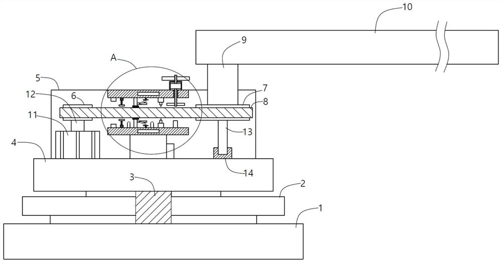
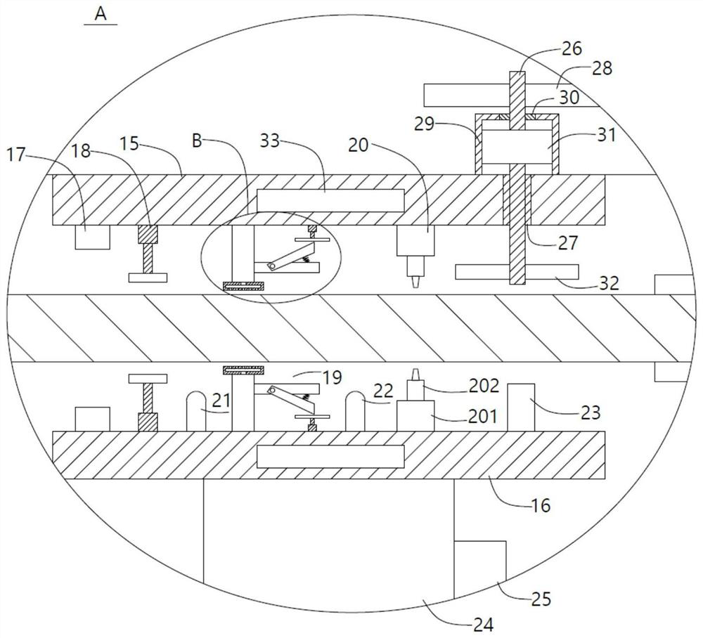
[0031] A tower crane slewing transmission mechanism, comprising a lower slewing platform 1, a slewing support 2 is arranged on the lower slewing platform 1, a connecting shaft 3 is embedded in the slewing support 2, an upper slewing platform 4 is arranged on the connecting shaft 3, and the upper slewing A deceleration transmission box 5 is arranged above the platform 4, and a rotating gear 6 and a deceleration gear 7 are hinged inside the deceleration transmission box 5. The gear ratio of the rotating gear 6 and the deceleration gear 7 should be reasonably set, so that the deceleration gear 7 rotates one circle. The time it takes is much longer than the time it takes for the rotating gear 6 to make one rotation, thereby realizing deceleration transmission. The transmission between the rotating gear 6 and the deceleration gear 7 is carried out through the transmission belt 8, and a support rod is fixed at the top center of the deceleration gear 7. 9. A boom 10 is fixed on the su...
Embodiment 2
[0034] On the basis of the first embodiment, the present embodiment further defines and discloses the relevant power structure and support structure for the transmission of the rotating gear 6 and the reduction gear 7 through the transmission belt 8: the inside of the reduction gear box 5 is fixedly provided with a rotating motor 11. The rotary motor 11 can use the D57BLD69-24A-15S model produced by Guangzhou Demark Motor Co., Ltd. The output shaft 12 of the rotary motor 11 is fixed at the bottom center of the rotary gear 6, and the bottom center of the reduction gear 7 is fixedly provided with The column 13 is hingedly arranged in the bearing seat 14, so the column 13 can rotate in the bearing seat 14, and the bearing seat 14 is fixedly arranged in the reduction gear box 5. It can be seen that the bearing seat 14 here mainly plays a supporting role.
Embodiment 3
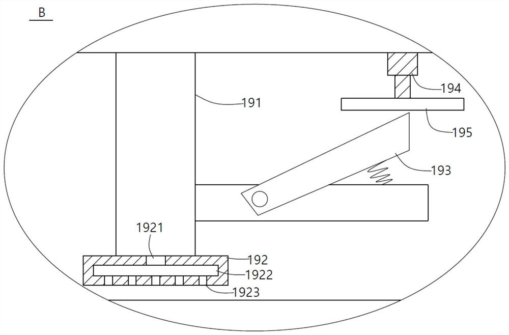
[0036] The hot-melt glue reinforcement device 19 includes a hot-melt glue gun main body 191 , an outlet end of the hot-melt glue gun main body 191 is provided with a glue outlet 192 , a glue inlet 1921 is opened in the glue outlet plate 192 , and the bottom of the glue inlet 1921 is communicated with each other. There is a glue storage cavity 1922, the bottom of the glue storage cavity 1922 is connected with a plurality of glue outlet holes 1923, the hot melt glue gun main body 191 is provided with an elastically connected pressing handle 193, the opposite sides of the upper mounting plate 15 and the lower mounting plate 16 The cylinders 194 are fixedly provided, and the cylinders 194 can adopt the MAL model of the Meile brand. It should be noted that the specific models of the electrical equipment are described in the various embodiments of this application, but the temperature and humidity of the actual use scene are used. The actual selection can be flexibly changed, so the ...
PUM
 Abstract
Description
Claims
Application Information
 - R&D
- Intellectual Property
- Life Sciences
- Materials
- Tech Scout
- Unparalleled Data Quality
- Higher Quality Content
- 60% Fewer Hallucinations
Browse by: Latest US Patents, China's latest patents, Technical Efficacy Thesaurus, Application Domain, Technology Topic, Popular Technical Reports.
© 2025 PatSnap. All rights reserved.Legal|Privacy policy|Modern Slavery Act Transparency Statement|Sitemap|About US| Contact US: help@patsnap.com


