
Milling device capable of detecting wear state of cutter and applied to machining of special-shaped crank arm

A tool wear and milling device technology, which is applied in the direction of manufacturing tools, metal processing equipment, metal processing machinery parts, etc., can solve the problems of crank arm shaking, affecting milling accuracy, clamping, etc., to achieve stable clamping and facilitate all-round milling Effect

Inactive Publication Date: 2020-12-04
东莞市龙飞数控科技有限公司
View PDF0 Cites 2 Cited by
  • Summary
  • Abstract
  • Description
  • Claims
  • Application Information

AI Technical Summary

Problems solved by technology

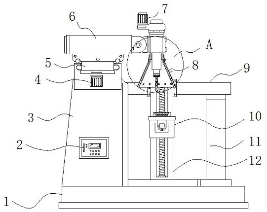
[0003] Existing milling machines can only clamp and mill workpieces with regular shapes. For special-shaped crank arms, their external shapes are irregular after milling, so the original clamps for clamping metal blocks cannot clamp them. It is easy to shake under the pressure of milling, which affects the precision of milling

Method used


Image

  • Milling device capable of detecting wear state of cutter and applied to machining of special-shaped crank arm
  • Milling device capable of detecting wear state of cutter and applied to machining of special-shaped crank arm
  • Milling device capable of detecting wear state of cutter and applied to machining of special-shaped crank arm

Examples


Embodiment Construction

[0026] The following will clearly and completely describe the technical solutions in the embodiments of the present invention with reference to the accompanying drawings in the embodiments of the present invention. Obviously, the described embodiments are only some, not all, embodiments of the present invention.

[0027] In the description of the present invention, unless otherwise stated, the meaning of "plurality" is two or more; the terms "upper", "lower", "left", "right", "inner", "outer" , "front end", "rear end", "head", "tail", etc. indicate the orientation or positional relationship based on the orientation or positional relationship shown in the drawings, and are only for the convenience of describing the present invention and simplifying the description, rather than Indicates or implies that the device or element referred to must have a particular orientation, be constructed and operate in a particular orientation, and therefore should not be construed as limiting the...


PUM


Abstract

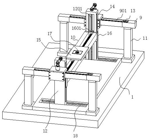
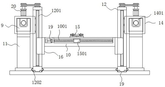
The invention discloses a milling device capable of detecting the wear state of a cutter and applied to machining of a special-shaped crank arm. The milling device specifically comprises a base plate,a protective cover, a milling base and the special-shaped crank arm; supporting columns are correspondingly installed at the four corners of the top of the base plate; a supporting base is fixed to the middle position of one end of the top of the base plate; longitudinal guide rails are correspondingly installed at the top ends of the supporting columns positioned at the two sides of the supporting base; the longitudinal guide rails are each sleeved with a movable base; the ends, close to the supporting base, of the movable bases are each fixedly provided with a vertical guide rail; lifting bases are installed on the vertical guide rails correspondingly; according to the milling device capable of detecting the wear state of the cutter and applied to machining of the special-shaped crank arm, by arranging two clamping bases which are each internally provided with a first clamping groove and a second clamping groove, raw material blocks can be clamped, and milled special-shaped crank arms can be clamped as well; milling cannot be blocked while stable clamping is achieved, so all-directional milling of the special-shaped crank arm is facilitated, a better clamping effect is achieved,and the machining difficulty is reduced.

Description

technical field [0001] The invention relates to the technical field of processing special-shaped parts, in particular to a milling device capable of detecting the wear state of a tool for processing special-shaped crank arms. Background technique [0002] The crank arm is one of the commonly used parts on the machine equipment. It is usually connected with other parts by screws to realize joint movement and other functions. The processing of the crank arm is relatively complicated, and it usually needs to be milled, drilled, reamed, and polished. The milling step is to mill the regular cuboid raw metal block into the shape of the required crank arm, which is usually divided into two steps, the first is to clamp the lower half of the raw metal block, mill the upper half, and the second is to turn over the raw material block, clamping the milled original upper half, and milling the original lower half. [0003] Existing milling machines can only clamp and mill workpieces with...

Claims


Application Information

Patent Timeline
IPC IPC(8): B23Q17/09
CPCB23Q17/0957
Inventor 龙建宇谢燕珊孟祥星
Owner 东莞市龙飞数控科技有限公司
Learn More