
Cutter wear prediction method based on milling power

A tool wear and prediction method technology, applied in special data processing applications, instruments, electrical digital data processing, etc., can solve the lack of universality and persuasiveness, the principle of the influence of wear and milling power has not been studied, and it is difficult to accurately predict tool wear conditions and other issues, to achieve the effect of high fit, high application value and accurate model

Pending Publication Date: 2021-11-12
NORTHWESTERN POLYTECHNICAL UNIV
View PDF8 Cites 0 Cited by
  • Summary
  • Abstract
  • Description
  • Claims
  • Application Information

AI Technical Summary

Problems solved by technology

The document "Shi K N, Zhang D H, Liu N, et al. A Novel Energy Consumption Model for Milling Process Considering Tool Wear Progression[J]. Journal of Cleaner Production, 2018, 184:152-159." proposed a milling power-based Tool wear prediction method, which uses linear regression method to directly establish the functional relationship between milling power and tool wear, and does not study the principle of the influence of wear on milling power, and the functional relationship under each set of parameters needs to be recalibrated , this method lacks universality and persuasiveness, and it is difficult to accurately predict the tool wear in actual machining

Method used


Image

  • Cutter wear prediction method based on milling power
  • Cutter wear prediction method based on milling power
  • Cutter wear prediction method based on milling power

Examples


Embodiment Construction

[0055]In describing the present invention, it should be understood that the terms "center", "longitudinal", "transverse", "length", "width", "thickness", "upper", "lower", "front", " Back", "Left", "Right", "Vertical", "Horizontal", "Top", "Bottom", "Inside", "Outside", "Clockwise", "Counterclockwise", etc. or The positional relationship is based on the orientation or positional relationship shown in the drawings, which is only for the convenience of describing the present invention and simplifying the description, rather than indicating or implying that the referred device or element must have a specific orientation, be constructed and operated in a specific orientation, Therefore, it should not be construed as limiting the invention.

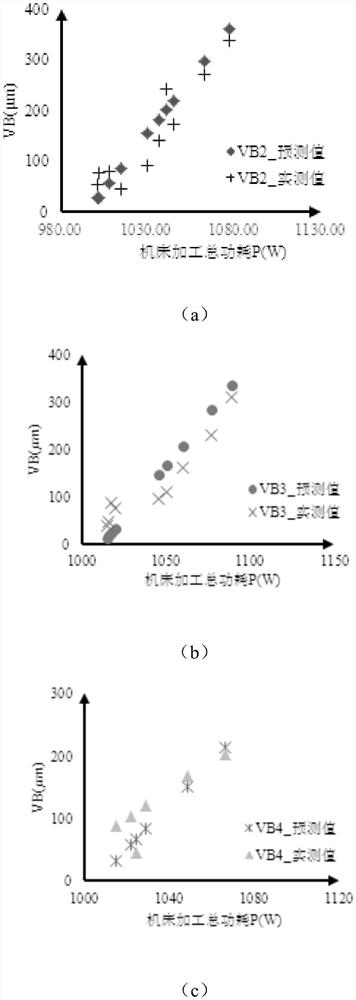
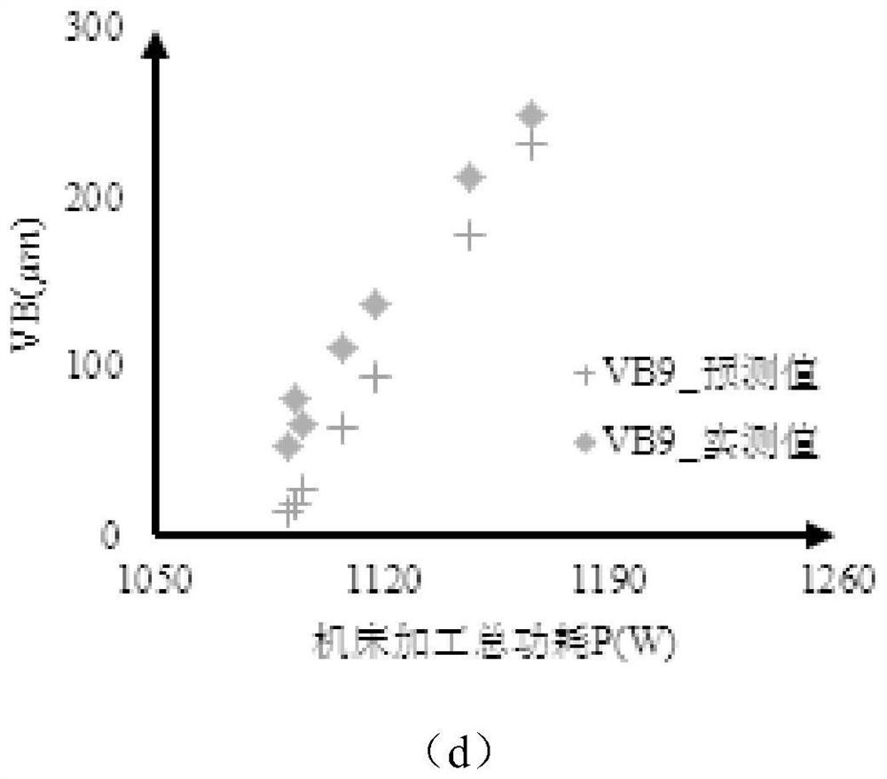
[0056] join figure 1 , this method first establishes a power consumption model based on milling force considering tool wear, and then based on the power consumption model, by ignoring the influence of feed power consumption, a tool wear model...


PUM


Abstract

The invention relates to a cutter wear prediction method based on milling power. The method comprises the following steps: firstly, establishing a milling force-based power consumption model considering tool wear, and then establishing a milling power-based tool wear prediction model by neglecting the influence of feeding power consumption and adopting a reverse thrust method based on the power consumption model. According to the method, the tool wear in the milling process of the numerical control machine tool is predicted, high prediction precision can be obtained in the middle and later periods of tool wear, and a reliable basis can be provided for the opportunity of tool replacement.

Description

technical field [0001] The invention belongs to the field of mechanical processing, in particular to a tool wear prediction method based on milling power. Background technique [0002] In the process of processing difficult-to-machine materials, the interaction between the tool and the workpiece will lead to a series of defects such as severe tool wear, short tool life, low productivity, and high energy consumption. Among them, severe tool wear leads to frequent tool changes. It is the direct factor that limits the processing efficiency. And in the actual processing of difficult-to-machine materials, severe tool wear will also seriously damage the processing quality of the part surface. When the tool wear exceeds the preset wear limit threshold during processing and the tool is not replaced in time, it will seriously affect the processed parts. Surface quality and processing errors will reduce the service life and reliability of key structural parts of aero-engines, and may...

Claims


Application Information

Patent Timeline
Patent Type & Authority Applications(China)
IPC IPC(8): G06F30/20G06F30/17G06F119/06G06F119/14
CPCG06F30/20G06F30/17G06F2119/14G06F2119/06
Inventor 吴宝海张思琪徐健谭淼龙燕直
Owner NORTHWESTERN POLYTECHNICAL UNIV
Learn More