
Manufacturing method of optical filter assembly, camera module and manufacturing method of camera module

A technology of a camera module and a manufacturing method, which is applied in the directions of electrical components, image communication, color TV components, etc., can solve the problems of the filter 101 falling off, insufficient connection strength, low production efficiency, etc., and avoid falling off and breaking. The effect of reducing cracking, reducing the use of processes and equipment, and improving production efficiency

Active Publication Date: 2021-02-09
NINGBO SEMICON INT CORP
View PDF5 Cites 0 Cited by
  • Summary
  • Abstract
  • Description
  • Claims
  • Application Information

AI Technical Summary

Problems solved by technology

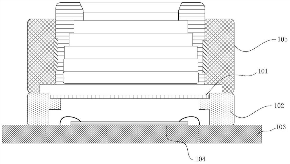
[0003] The optical filter and bracket in the traditional camera are separately customized. In the traditional packaging process, the optical filter 101 and the bracket 102 are attached together by dispensing, which involves many processes, high cost and low production efficiency. The way of glue bonding is likely to cause insufficient connection strength between the optical filter 101 and the bracket 102, and the hidden danger of the optical filter 101 falling off and breaking

Method used


Image

  • Manufacturing method of optical filter assembly, camera module and manufacturing method of camera module
  • Manufacturing method of optical filter assembly, camera module and manufacturing method of camera module
  • Manufacturing method of optical filter assembly, camera module and manufacturing method of camera module

Examples


Embodiment Construction

[0057] The present invention will be described in more detail below with reference to the accompanying drawings. Although preferred embodiments of the invention are shown in the drawings, it should be understood that the invention may be embodied in various forms and should not be limited to the embodiments set forth herein. Rather, these embodiments are provided so that this disclosure will be thorough and complete, and will fully convey the scope of the invention to those skilled in the art.

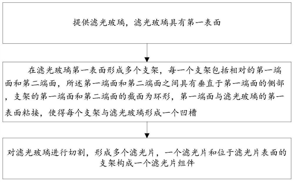
[0058] figure 2 A flow chart showing the steps of a method for manufacturing an optical filter assembly of the present invention.

[0059] like figure 2 Shown, a kind of manufacturing method of optical filter assembly of the present invention comprises:

[0060] providing a filter glass 201, the filter glass 201 has a first surface;

[0061] A plurality of brackets 205 are formed on the first surface of the filter glass 201, and each bracket 205 includes a first end surface and a...


PUM


Abstract

The invention discloses a manufacturing method of an optical filter assembly, a camera module packaging method and a camera module. The method comprises the steps that light filtering glass is provided, a plurality of supports are formed on the first surface of the light filtering glass, each support comprises a first annular end face and a second annular end face which are opposite, a side portion perpendicular to the first end face is arranged between the end faces, and the first end face is bonded with the first surface of the light filtering glass and forms a groove with the light filtering glass; and cutting the filter glass to form a plurality of filter assemblies. The camera module comprises a substrate; the photosensitive element is arranged on the substrate and is electrically connected with the substrate; one end, far away from the optical filter, of the support is arranged on the substrate, the optical filter, the support and the substrate form a closed cavity, and the photosensitive element is located in the cavity; the lens and the motor are arranged above the optical filter. According to the invention, the optical filter assembly with the integrated structure of the bracket and the optical filter is formed in batches, so that the procedures for manufacturing the camera module are reduced, and the manufacturing cost is reduced.

Description

technical field [0001] The present invention relates to the field of camera manufacturing, and more specifically, to a method for manufacturing an optical filter assembly, a camera module and a method for manufacturing the same. Background technique [0002] like figure 1 As shown, the optical filter 101 and the bracket 102 (base) in the existing terminal camera are manufactured separately, and the optical filter 101 is made by cutting the entire filter glass into a plurality of small filter chips (chips) The bracket 102 is mass-produced by injection molding and other processes. In the camera packaging process, the CIS chip 104 (cmos image sensor) is first mounted on the front of the substrate 103, and then the bottom of the bracket 102 is bonded to the front of the substrate 103 to make the CIS The chip 104 is located in the bracket 102 , and then the optical filter 101 is fixed on the bracket 102 through glue coating and baking process, and finally the lens and the motor ...

Claims


Application Information

Patent Timeline
Patent Type & Authority Applications(China)
IPC IPC(8): H04N5/225
CPCH04N23/54H04N23/50H04N23/55
Inventor 龚罗炜
Owner NINGBO SEMICON INT CORP
Learn More