Electrical Connector Tray

An electrical connector and tray technology, which is applied in the field of low-profile electrical connector trays, can solve the problems of material waste in the production process, cumbersomeness, and increased material consumption, so as to reduce the cost of packaging materials and transportation costs, and increase the storage density. , the effect of reducing the use of materials

Active Publication Date: 2017-07-28
FOXCONN (KUNSHAN) COMPUTER CONNECTOR CO LTD +1
View PDF10 Cites 0 Cited by
  • Summary
  • Abstract
  • Description
  • Claims
  • Application Information

AI Technical Summary

Problems solved by technology

[0006] The staggered stacking structure has a space-saving and stable storage function for storing small-sized electrical connectors or electronic components, but for larger-sized electrical connectors and other storage parts, the staggered stacking structure wi

Method used


Image

  • Electrical Connector Tray
  • Electrical Connector Tray
  • Electrical Connector Tray

Examples


Embodiment Construction

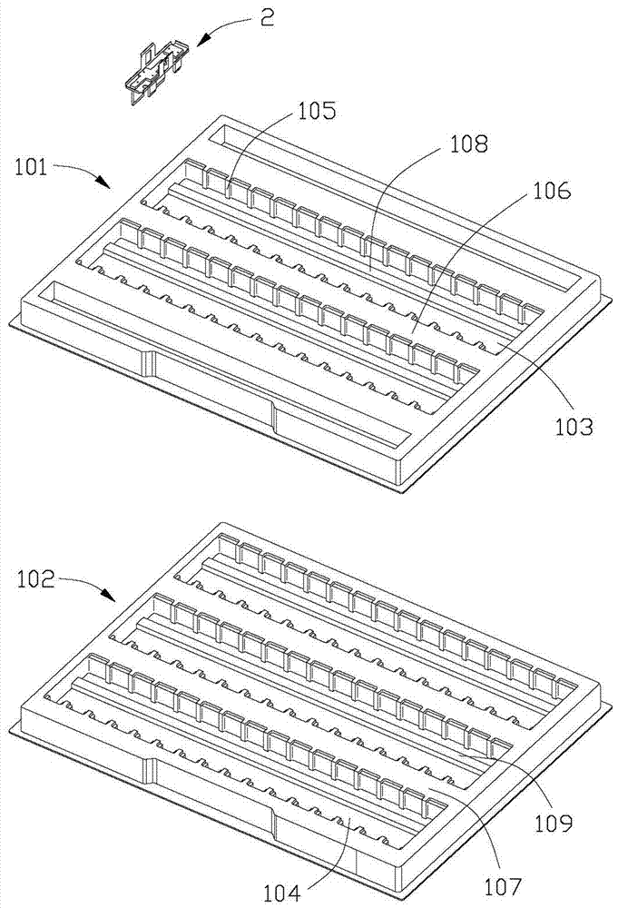
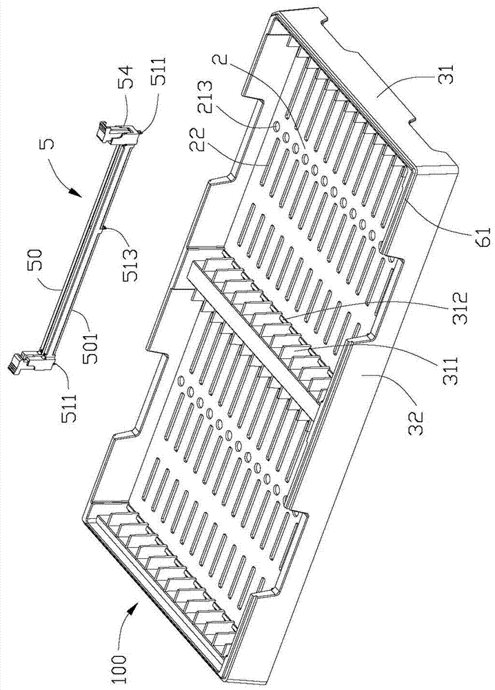
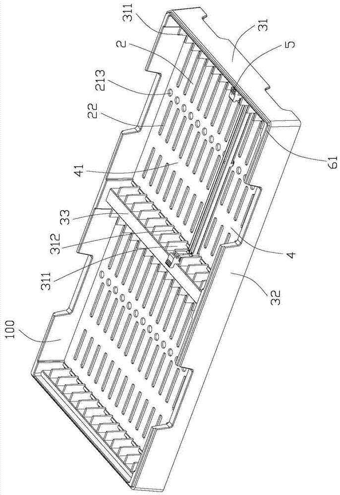
[0019] see figure 2 As shown, the electrical connector tray 100 is used for packing and transporting the electrical connectors 5 . The electrical connector 5 includes a lengthwise insulating body 50, several terminal slots (not shown) arranged side by side along the longitudinal direction of the insulating body 50, and several terminals (not shown) inserted in the terminal slots (not shown). Show). Two locking arms 54 extend vertically from both ends of the insulating body 50 in the longitudinal direction. The insulating body 50 has a bottom 501 , and the insulating body 50 also has a limiting hook 513 vertically extending out of the insulating body 50 from the bottom 501 . The terminals (not shown) are provided with pins (not shown) extending vertically from the bottom 501 of the insulating body 50 to solder the electrical connector 5 to a circuit board (not shown). In this embodiment, the insulating body 50 is further provided with fixing hooks 511 perpendicularly extend...


PUM


Abstract

An electrical connector tray, especially a tray of low-profile electrical connectors. The tray includes a bottom plate, several side walls protruding from the bottom plate, and a receiving space formed by the side walls, and the receiving space is provided with several receiving grooves for receiving electrical connectors. The tray is provided with a limiting through hole that runs through the bottom plate and communicates with the accommodating groove, so as to accommodate the hook structure of the storage parts such as electrical connectors, so as to reduce the space occupied by the storage parts, and the limiting through hole is biased towards One side of the accommodating groove is used to prevent the electrical connector from being reversed or misplaced.

Description

[0001] 【Technical field】 [0002] The invention relates to an electrical connector tray, in particular to a low profile electrical connector tray. [0003] 【Background technique】 [0004] Pallets or boxes are usually used to package items to facilitate handling or transportation while also preventing damage to the items. [0005] Please refer to figure 1 As shown, in the prior art, the packaging tray or tray 1 is a combined tray, including a number of upper trays 101 and lower trays 102 with concave-convex structures pressed by thin plate materials, wherein the upper and lower trays 101, 102 are respectively recessed. Rows of storage slots 103, 104, each storage slot 103, 104 is divided into storage spaces for several storage objects 2 by several transverse ribs 105 arranged on its side walls, and there is a partition between two adjacent rows of storage slots. Wall 106, the upper wall 101 and the lower wall 102 are mutually stacked, and when the two are stacked and combined,...

Claims


Application Information

Patent Timeline
IPC IPC(8): B65D85/86B65D25/02B65D21/032
Inventor 徐琴唐文军卜学武
Owner FOXCONN (KUNSHAN) COMPUTER CONNECTOR CO LTD
Why Eureka
Try Eureka