
Parking spot lock

A technology for parking locks and rotating nodes, applied in the field of parking locks

Inactive Publication Date: 2014-06-25
薛旭忠
View PDF7 Cites 4 Cited by
  • Summary
  • Abstract
  • Description
  • Claims
  • Application Information

AI Technical Summary

Problems solved by technology

[0003] The purpose of the present invention is to provide a technical solution for a parking space lock to solve the defects and deficiencies of manual opening and closing of the lock when using the existing ground lock technology, so as to realize that the driver can remotely control the parking space support in the car put up or down

Method used


Image

  • Parking spot lock
  • Parking spot lock

Examples


Embodiment Construction

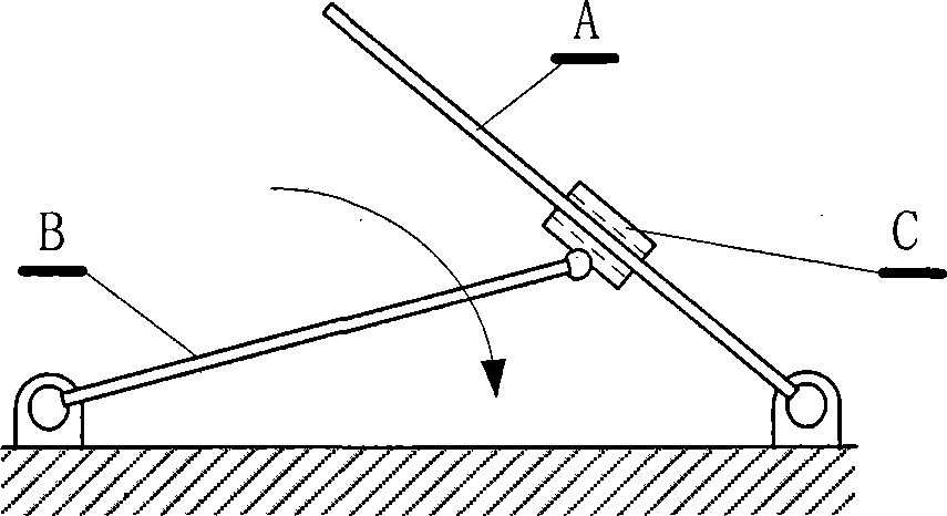
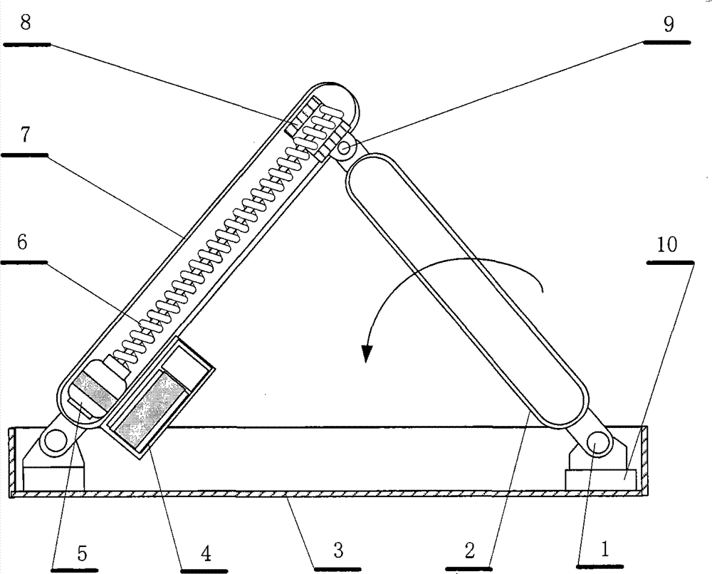
[0009] attached figure 2 It is an embodiment that the parking lock adopts a triangular structure; the system consists of a remote controller and an electric parking lock with a remote control receiving device. The parking lock includes a rotating node 1, a bracket 2, a base box 3, a control box 4, a motor 5, and a screw rod 6. Bracket 7, sliding module 8, rotating node 9, node seat 10; the remote control communication method can adopt "Bluetooth", "WIFI" or other existing high-frequency wireless control technology; the electric parking lock part is composed of a control part and an execution part; the control Part is installed and sealed in the control box 4, including remote control signal receiving, signal processing, power booster and battery; there is a transparent sealed observation window on the control box 4, and the remote control signal receiving head is close to the transparent window, or through the signal line, the The remote control signal receiving head is place...


PUM


Abstract

The invention discloses a parking spot lock, and belongs to the technical field of vehicle management equipment. A system is composed of an in-vehicle remote control unit and a remote control parking spot lock body. The parking spot lock is characterized in that when a motor rotates, a support is driven to ascend or descend, and when the support rises, a triangular parking space is formed.

Description

technical field [0001] A parking lock belongs to the technical field of vehicle management equipment. Background technique [0002] In recent years, with the continuous improvement of people's lives, there are more and more private cars, and there are more and more disputes over parking spaces. In order to protect their parking spaces from being occupied by other cars, many car owners have installed Ground lock, the existing ground lock technology requires that when the car drives away, the driver gets off the car and sets up the ground lock bracket, and locks the bracket with a lock before leaving; Only when the lock is opened and the support is put down, the car can drive back to the parking space. This technical defect and deficiency bring many troubles in use to the user. Contents of the invention [0003] The purpose of the present invention is to provide a technical solution for a parking space lock to solve the defects and deficiencies of manual opening and closing...

Claims


Application Information

Patent Timeline
IPC IPC(8): E04H6/42
Inventor 薛旭忠许增辉钟茂干
Owner 薛旭忠
Learn More