Large mechanical test system for combined adjustable constraint concrete arch frame

A mechanical test and adjustable technology, used in shaft equipment, shaft lining, mining equipment, etc., can solve the problems of arch failure, increased cost, high hydraulic measurement and control accuracy, and achieve reduced stress concentration, sufficient contact, and good stability. Effect

Active Publication Date: 2014-06-25
SHANDONG UNIV +1
View PDF8 Cites 28 Cited by
  • Summary
  • Abstract
  • Description
  • Claims
  • Application Information

AI Technical Summary

Problems solved by technology

[0005] 1. The size is too small to realize a 1:1 large-scale test or a large-scale simulation test. It is necessary to reduce the support frame used on site according to a certain scale and process a special arch frame for the test. The test cannot be carried out directly, which makes the test process More complex, lower test accuracy, and higher cost
[0006] 2. The model device can only meet the arch test of one shape, and cannot meet the requirements of diversified arch shapes;
[0007] 3. The size of the arch frame that can be tested by the model test device has fixed requirements and cannot be changed at will, let alone directly test the arch frame used on site;
[0008] 4. Most of the loading systems cannot achieve the effect of flexible loading, so that the force transmission pressure head forms a rigid contact with the surface of the arch, and even produces line contact or point contact after deformation, causing the arch to fail due to stress concentration. Accuracy has a big impact
[0009] Generally speaking, for the increasingly complex underground projects such as deep or soft rock roadways, tunnels, chambers, etc., there are still some problems in the existing test bench device system, which cannot realize large size, different shapes, high load, hydraulic pressure, etc. Due to the characteristics of high measurement and control precision and accurate monitoring and acquisition, a new type of combined adjustable constrained concrete arch large-scale mechanical test system is needed to solve the above problems

Method used


Image

  • Large mechanical test system for combined adjustable constraint concrete arch frame
  • Large mechanical test system for combined adjustable constraint concrete arch frame
  • Large mechanical test system for combined adjustable constraint concrete arch frame

Examples


Embodiment

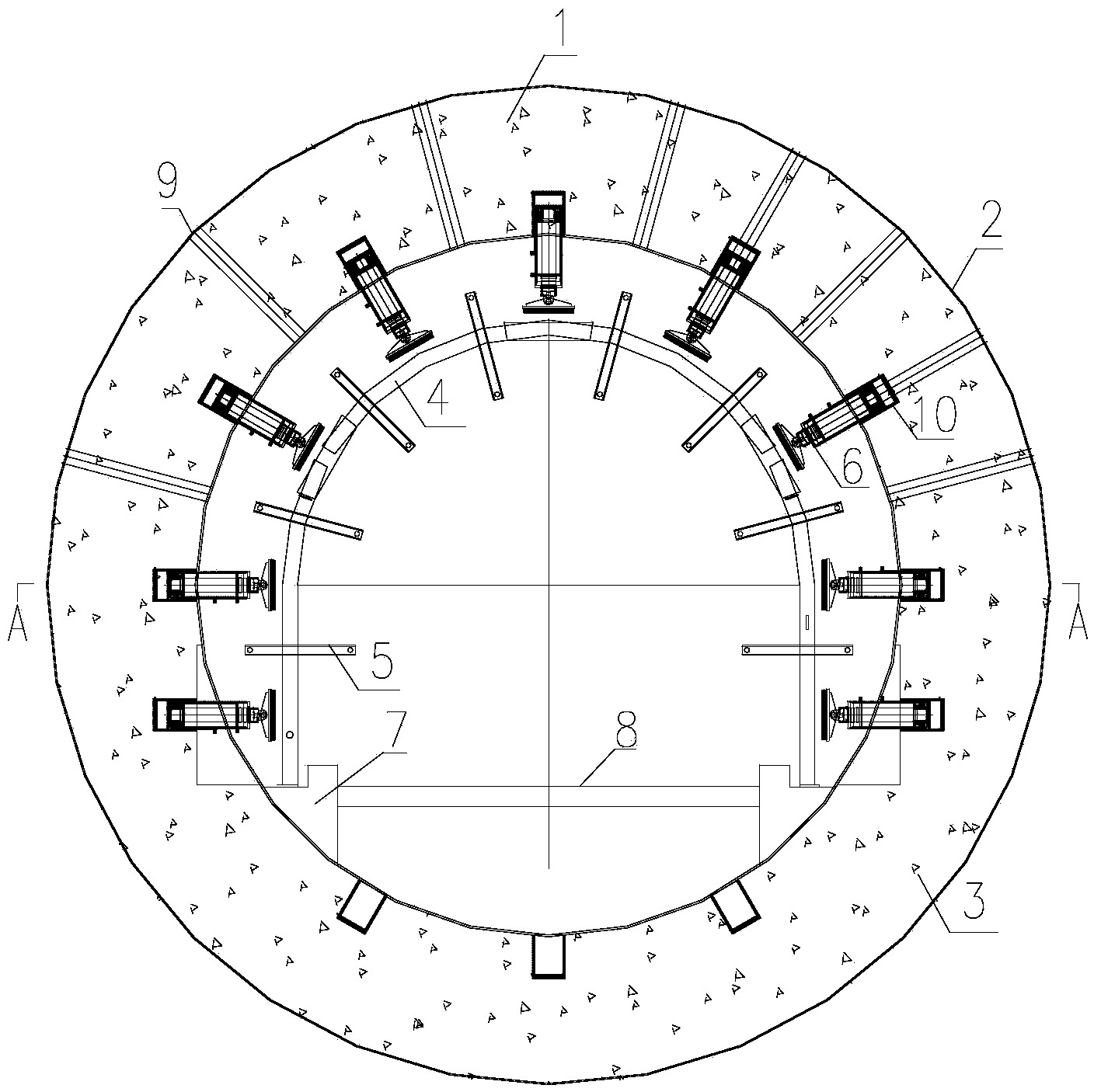
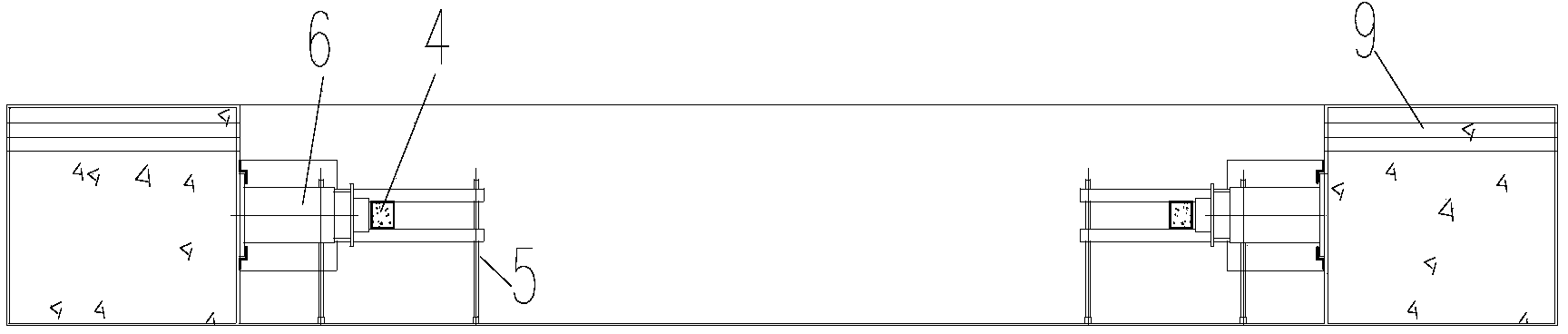
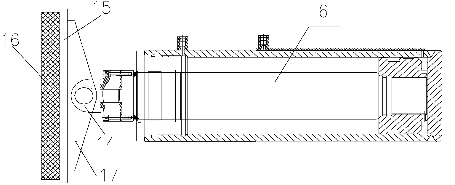
[0044] Combined adjustable constrained concrete arch large-scale mechanical test system, including monitoring system for monitoring and collecting arch parameter data, hollow cylindrical reaction force structure 1, hydraulic loading device, auxiliary loading device, inner cylindrical surface of reaction force structure 1 A plurality of oil cylinder positioning holes 10 are distributed on the top, and a hydraulic loading device is fixed in the oil cylinder positioning holes 10. The hydraulic loading device includes a hydraulic cylinder 6 in the oil cylinder positioning hole 10, a force transmission dispersion device connected to the hydraulic cylinder 6 and a control system. , the hydraulic cylinder 6 is loaded by contacting the arch frame to be tested through the force transmission and dispersion device.

[0045] The reaction force structure 1 is welded by steel plates 2 and filled with concrete 3 inside. Twelve oil cylinder positioning holes 10 are arranged on the reaction fo...


PUM


Abstract

The invention relates to a large mechanical test system for a combined adjustable constraint concrete arch frame. The system comprises a monitoring system, a hollow cylindrical counter force structure, a hydraulic loading device and an auxiliary loading device, wherein the monitoring system is used for monitoring and collecting arch frame parameters and data. The inner cylindrical surface of the counter force structure is provided with multiple oil cylinder positioning holes, the hydraulic loading device is disposed in the oil cylinder positioning holes, the hydraulic loading device comprises a hydraulic oil cylinder arranged in the oil cylinder positioning holes, a force transmission dispersion device connected with the hydraulic oil cylinder and a control system, and the hydraulic oil cylinder achieves loading through contact of the force transmission dispersion device and an arch frame to be tested. By means of the system, a 1:1 mechanical test can be carried out on the constraint concrete arch frame and other conventional arch frames, and tests of arch frames of different sizes and shapes can be achieved.

Description

technical field [0001] The invention relates to a large-scale mechanical test system of a combined adjustable constrained concrete arch, which belongs to the field of mechanical tests of underground engineering support materials. Background technique [0002] With the development of our country's economy and society, more and more underground mines, tunnels, subways, hydropower chambers, etc. are being built, and the support problems faced by them are becoming more and more prominent. Especially when the burial depth and section design are large, or in some weak strata, the surrounding rock is loose and broken, and the self-stabilization time of the surrounding rock after excavation is short, while the traditional bolt, shotcrete or steel arch, Failure to provide sufficient initial support resistance in time will cause serious deformation of the surrounding rock or even collapse and damage. Therefore, in order to maintain the stability of the surrounding rock, it is necessar...

Claims


Application Information

Patent Timeline
Patent Type & Authority Applications(China)
IPC IPC(8): E21D11/10
Inventor 李术才王琦李为腾王培军王新邵行张波曾艳君
Owner SHANDONG UNIV
Why Eureka
Try Eureka