Backlight module and liquid crystal display device

A technology of backlight module and light guide plate, which is applied in optics, nonlinear optics, instruments, etc., can solve the problems of low brightness of backlight source, increased gap between LED and light guide plate, etc., and achieve the effect of ensuring high efficiency and high yield rate

Active Publication Date: 2017-02-15
BOE TECH GRP CO LTD +1
View PDF6 Cites 0 Cited by
  • Summary
  • Abstract
  • Description
  • Claims
  • Application Information

AI Technical Summary

Problems solved by technology

[0008] The technical problem to be solved by the present invention is how to avoid the problem that the brightness of the backlight source is too low due to the increase in the gap between the LED and the light guide plate caused by the deformation of the light guide plate during the use of the backlight module

Method used


Image

  • Backlight module and liquid crystal display device
  • Backlight module and liquid crystal display device
  • Backlight module and liquid crystal display device

Examples


Embodiment 1

[0031] like figure 2 As shown, a backlight module according to an embodiment of the present invention includes a light guide plate, an LED lamp, and an outer frame 10 for assembling the light guide plate and the LED lamp. One side of the light guide plate is a light incident surface, which is opposite to the position of the LED lamp An elastic piece in a compressed state is provided between the side of the light guide plate opposite to the light-incident surface and the outer frame 10, and a slot 11 is provided on the inner side of the outer frame 10 in contact with the elastic piece, and the slot 11 is used for installing The elastic part is used to position the elastic part to prevent the elastic part from shifting and ensure the elastic contact between the elastic part and the light guide plate. The elastic part can be directly placed in the slot without any other such as gluing or fastening The connection of parts, etc. can simplify the process.

[0032] The outer frame ...

Embodiment 2

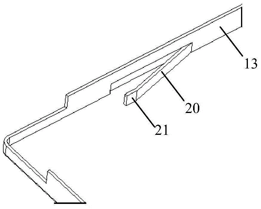
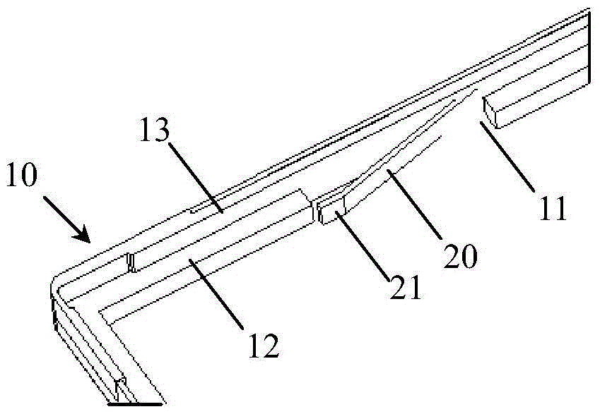
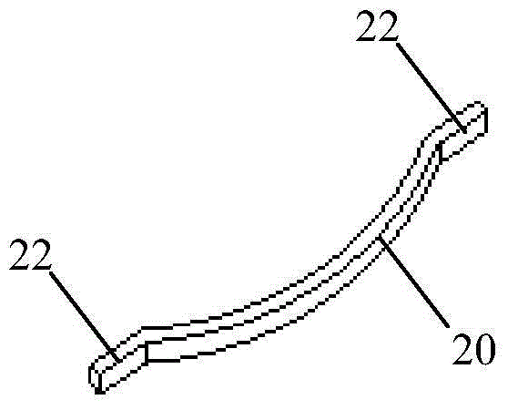
[0038] like image 3 As shown, a backlight module according to an embodiment of the present invention includes a light guide plate, an LED lamp, and an outer frame 10 for assembling the light guide plate and the LED lamp. One side of the light guide plate is a light incident surface, which is opposite to the position of the LED lamp An elastic member is provided between the side opposite to the light incident surface of the light guide plate and the outer frame 10. The elastic member in this embodiment is an arc-shaped elastic piece 20, and the two ends of the elastic piece 20 are connected to the slot 11, wherein The protruding part between them is in contact with the side of the light guide plate, and the elastic member can be directly placed in the slot without any other connections such as glue and fasteners, which can simplify the process.

[0039] Wherein, the outer frame 10 of this embodiment includes a plastic frame 12 and a metal outer frame 13 covering the outside of...


PUM


Abstract

The invention relates to the technical field of displaying, and discloses a backlight module and an LCD device. The backlight module comprises a light guide plate, an LED lamp and an outer frame used for assembling the light guide plate and the LED lamp. One side of the light guide plate is a light inlet surface which is opposite to the LED lamp in position. An elastic part which is in a compressed state is arranged between the side, opposite to the light inlet surface, of the light guide plate and the outer frame. The position, making contact with the elastic part, of the inner side of the outer frame is provided with a clamping groove which is used for installing the elastic part. According to the backlight module and the LCD device, the problem that the brightness of a backlight source is too low due to the fact that under existing technical conditions, the gap between the LED lamp and the light guide plate is overlarge is solved, high efficiency and high yield in the process of assembling the backlight source can be guaranteed, and meanwhile the phenomenon that in a reliability test (high temperature, high humidity and high and low temperature storage), the gap between the LED lamp and the light guide plate is enlarged due to thermal expansion and cold contraction of the light guide plate can be effectively avoided.

Description

technical field [0001] The invention relates to the field of display technology, in particular to a backlight module and a liquid crystal display device. Background technique [0002] In the backlight assembly, there is a certain gap (ie Gap) between the light guide plate (LGP) and the LED lamp, which is an important factor affecting the brightness of the backlight. In the existing backlight module, generally There is a certain gap between the light guide plate and the LED lamp by providing buckles and other methods between the light guide plate and the LED lamp. However, the larger the gap between the LED lamp and the light guide plate, the smaller the luminous brightness of the backlight source. The experimental test data proves that when the gap between the LED lamp and the light guide plate reaches 0.5mm, the luminance of the backlight is only 50% of the theoretical luminance. [0003] At present, there are mainly two solutions to solve the problem of too large gap bet...

Claims


Application Information

Patent Timeline
Patent Type & Authority Patents(China)
IPC IPC(8): G02F1/13357
Inventor 曾智辉董瑞君王子健
Owner BOE TECH GRP CO LTD
Why Eureka
Try Eureka