Plane light source

A flat lamp and substrate technology, which is applied to discharge lamps, gas discharge lamps, and parts of gas discharge lamps, etc., can solve problems such as low brightness, and achieve the effect of enhancing luminous brightness and solving darker brightness.

Inactive Publication Date: 2009-11-04
CPT TECH GRP
View PDF3 Cites 0 Cited by
  • Summary
  • Abstract
  • Description
  • Claims
  • Application Information

AI Technical Summary

Problems solved by technology

[0006] Therefore, the object of the present invention is to provide a planar light source, which can solve the shortcoming that the known planar light source has low brightness around it.

Method used


Image

  • Plane light source
  • Plane light source
  • Plane light source

Examples


Embodiment Construction

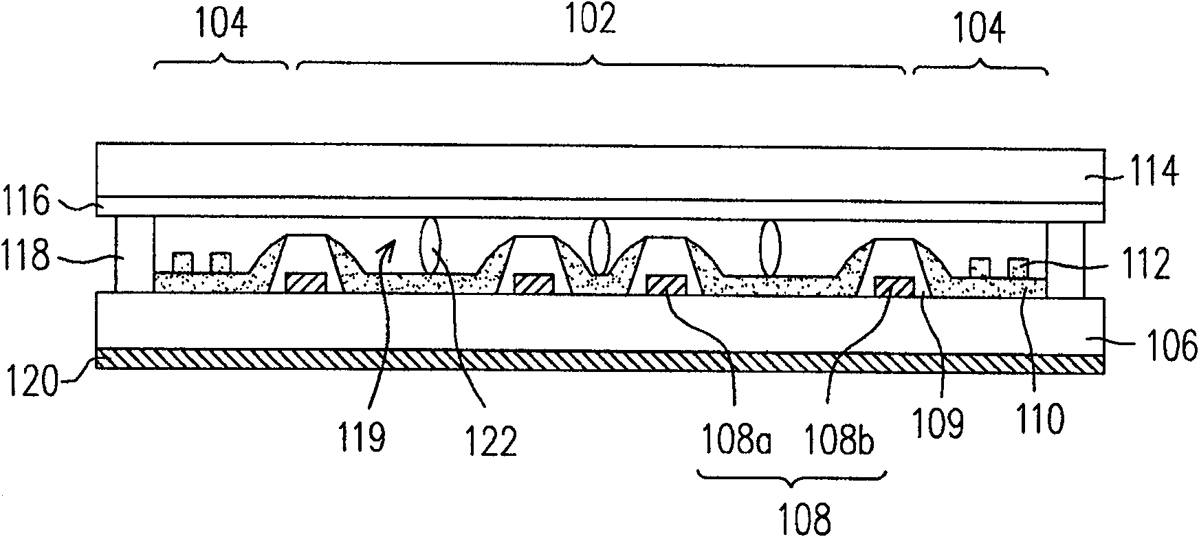
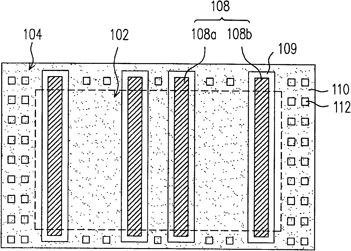
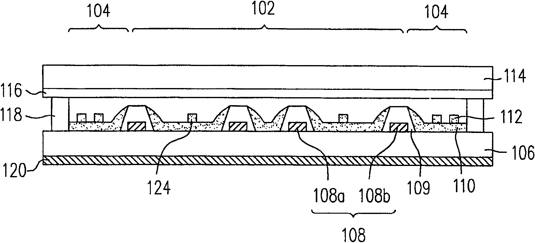
[0039] Figure 1A is a schematic cross-sectional view of a planar light source according to a preferred embodiment of the present invention. Figure 1B yes Figure 1A Top view of the first substrate in the planar light source. Please also refer to Figure 1A and Figure 1B , the planar light source of the present invention has a main body area 102 and an edge area 104 located around the main body area 102 . The planar light source includes a first substrate 106 , a plurality of first electrodes 108 , a second substrate 114 , a sealant 118 , a plurality of dielectric patterns 109 , a fluorescent layer 110 and a plurality of first fluorescent patterns 112 . The material of the first substrate 106 and the second substrate 114 is, for example, transparent glass. The frame glue 118 is disposed between the first substrate 106 and the second substrate 114 outside the edge area 104, and the frame glue 118 is used to join the two substrates 106, 114 together, so that the frame glue 1...


PUM

PropertyMeasurementUnit
heightaaaaaaaaaa

Abstract

A planar light source includes a main body area and an edge area around the main body area. The planar light source includes a first substrate, a plurality of first electrodes, a plurality of dielectric patterns, a fluorescent layer, a plurality of first fluorescent patterns, a second substrate and a plastic frame. The first electrode is configured on the first substrate, and the first electrode is arranged in the body area and the edge area. The dielectric pattern covers the first electrode on the first substrate. The phosphor layer is disposed between the dielectric patterns in the body area and the edge area. The first fluorescent pattern is configured on the fluorescent layer in the edge area. The second substrate is disposed above the first substrate. The glue frame is arranged between the first substrate and the second substrate and is located outside the edge area, so as to bond the first substrate and the second substrate together.

Description

technical field [0001] The present invention relates to a planar light source, and in particular to a planar light source with high brightness and high luminous uniformity. Background technique [0002] In recent years, most of the display screens are liquid crystal display panels (LCD panels). However, since the liquid crystal display panel itself does not have the function of emitting light, a backlight module (Back light module) must be provided under the liquid crystal display panel to provide a light source to achieve the display function. The light source in the backlight module is generally provided by a light-emitting tube, and the light emitted by the tube passes through the optical film in the backlight module and is scattered to form a surface light source suitable for illuminating the liquid crystal display panel. [0003] However, if the planar light source can be used directly, the utilization efficiency of light and a more uniform surface light source can be ...

Claims


Application Information

Patent Timeline
Patent Type & Authority Patents(China)
IPC IPC(8): H01J61/35H01J61/00G02F1/13357G02F1/1335
Inventor 谢宇恒丁初稷曾祥辉李素秋
Owner CPT TECH GRP
Why Eureka
Try Eureka