Wafer clamping device utilizing spring tensioning force feedback and motor driving force feedback

A technology of motor drive and clamping device, which is applied in the manufacture of circuits, electrical components, semiconductors/solid-state devices, etc. It can solve the problems that the wafer clamping device is not suitable for large-size wafers, wafer transmission pollution, etc., to ensure reliability Sexuality, avoiding cross-contamination, and solving the effect of transmission pollution

Active Publication Date: 2014-06-25
THE 45TH RES INST OF CETC
View PDF6 Cites 5 Cited by
  • Summary
  • Abstract
  • Description
  • Claims
  • Application Information

AI Technical Summary

Problems solved by technology

[0004] The purpose of the present invention is to provide a force feedback wafer clamping device using spring tension and motor drive, to solve the technical problem that the traditional wafe

Method used


Image

  • Wafer clamping device utilizing spring tensioning force feedback and motor driving force feedback
  • Wafer clamping device utilizing spring tensioning force feedback and motor driving force feedback
  • Wafer clamping device utilizing spring tensioning force feedback and motor driving force feedback

Examples


Embodiment Construction

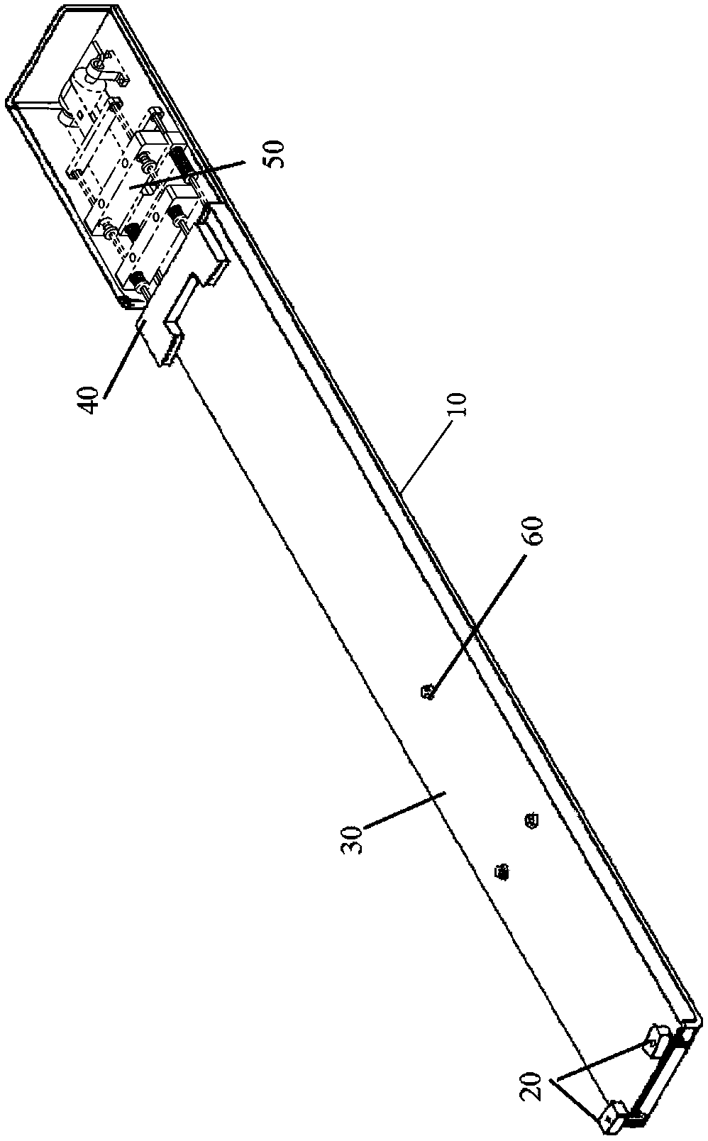
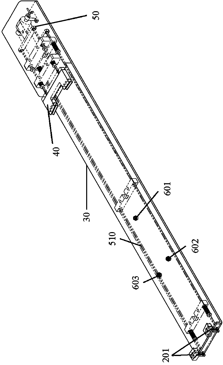
[0050] Examples see Figure 1-3 As shown, the force feedback wafer clamping device using spring tension and motor drive includes a base 10 and a front clamp 20 and a rear clamp 40 arranged on the base 10 for clamping a wafer. The base 10 is also provided with a driving mechanism 50 for controlling the movement of the front clamp 20 and the rear clamp 40 (ie, adjusting the clamping distance).

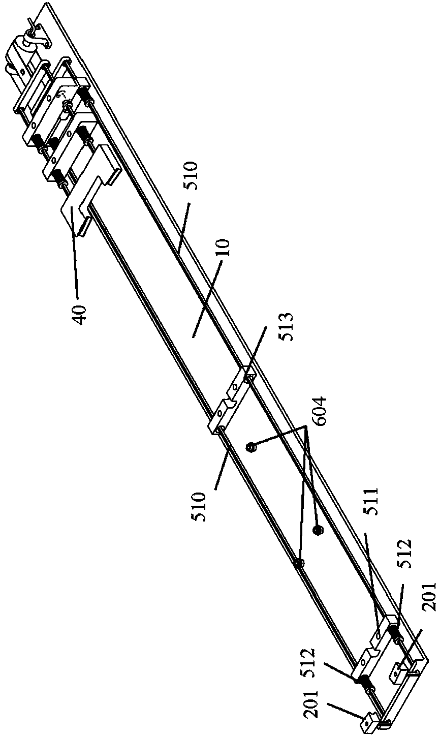
[0051] see Figure 3-6 , the driving mechanism 50 is made up of the front clip connection mechanism, the rear clip connection mechanism and the power source.

[0052] The power source is arranged on the base 10 behind the rear clamp 40, and includes a transmission belt 506 (synchronous belt or chain), a drive unit 507 and a drive unit support 508, and the drive unit 507 is placed on the base through the drive unit support 508 10, the transmission belt 506 is engaged with the drive unit 507, and is driven by the drive unit 507 to alternately reciprocate left and right, and one end of th...


PUM


Abstract

A wafer clamping device utilizing spring tensioning force feedback and motor driving force feedback comprises a base, a front clamp and a rear clamp, wherein the front clamp and the rear clamp are arranged on the base and used for clamping wafers, a driving mechanism used for controlling the front clamp and the rear clamp to move is further arranged on the base, the driving mechanism is composed of a front clamp connecting mechanism, a rear clamp connecting mechanism and a power source, the power source comprises a transmission belt, a driving unit and a driving unit support, the driving unit is placed on the base through the driving unit support, the transmission belt is meshed with the driving unit and reciprocates leftwards and rightwards alternately under the driving of the driving unit, one end of the transmission belt is connected with the front clamp through a rear spring tensioning mechanism, and the other end of the transmission belt is connected with the rear clamp through a front spring tensioning mechanism. The device effectively solves the problem of a vacuum absorption type clamping device that wafer transmission pollution can be caused due to the contact between the vacuum absorption type clamping device and the back sides of wafers, water clamping reliability is guaranteed, and cross contamination between wafers is avoided.

Description

technical field [0001] The invention relates to a wafer clamping device used in the wafer transmission link of semiconductor wafer processing equipment. Background technique [0002] In the process of semiconductor wafer processing, there are a large number of wafer transfer tasks between cassette-cassette and cassette-worktable, and the wafer clamping device, as a key component of wafer transfer, directly determines the transmission effect. [0003] Most of the existing wafer clamping devices are vacuum adsorption wafer clamping devices, but the vacuum adsorption wafer clamping device is in contact with the back of the wafer, which is easy to cause wafer transmission pollution, and is only suitable for small-sized wafers . Contents of the invention [0004] The purpose of the present invention is to provide a force feedback wafer clamping device using spring tension and motor drive, to solve the technical problem that the traditional wafer clamping device is easy to cau...

Claims


Application Information

Patent Timeline
IPC IPC(8): H01L21/687
CPCH01L21/6875
Inventor 徐存良高慧莹詹阳李伟
Owner THE 45TH RES INST OF CETC
Why Eureka
Try Eureka