
Low-resistance synchronous ring and synchronizer

A synchronous ring, low resistance technology, used in clutches, mechanical drive clutches, mechanical equipment, etc., can solve the problems of errors, affecting the uniformity of the synchronous ring force, obstacles, etc., to reduce the contact area, reduce resistance, and ensure uniformity. Effect

Inactive Publication Date: 2014-07-02
天津天海同步科技有限公司
View PDF6 Cites 6 Cited by
  • Summary
  • Abstract
  • Description
  • Claims
  • Application Information

AI Technical Summary

Problems solved by technology

[0003] However, due to errors in the manufacturing process of the spline teeth on the outer circumference of the synchronous ring, it is impossible for each spline tooth to seamlessly fit with the inner spline teeth on the gear sleeve during the shifting process, or even Causes obstacles and affects the overall force uniformity of the synchronous ring

Method used


Image

  • Low-resistance synchronous ring and synchronizer
  • Low-resistance synchronous ring and synchronizer
  • Low-resistance synchronous ring and synchronizer

Examples


Embodiment Construction

[0021] The specific embodiments created by the present invention will be described in detail below with reference to the accompanying drawings.

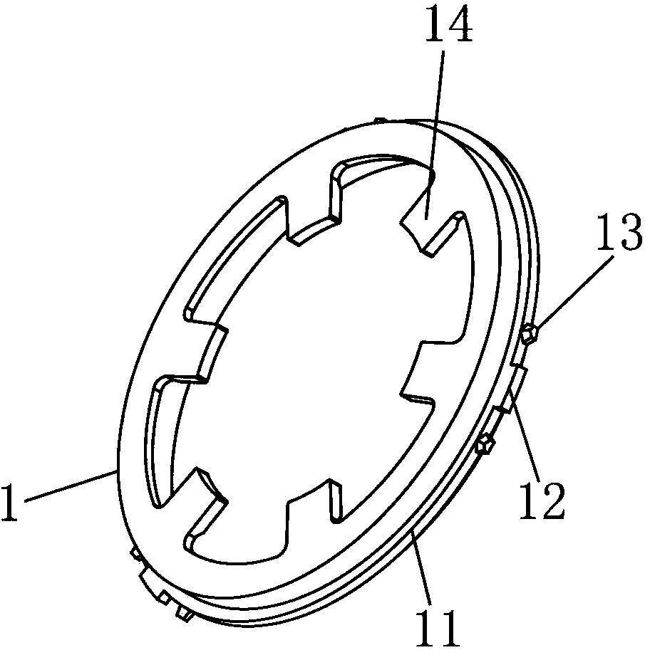
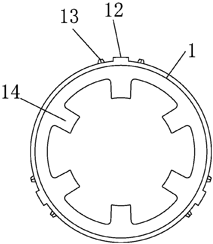
[0022] The design idea created by the present invention is to change the existing design idea of ​​completing synchronization and locking by controlling the multiple spline tooth directions in the gear sleeve to complete the synchronization and locking by sliding in the tooth grooves between the multiple coupling teeth on the synchronizing ring that matches it. , Changed to control the combination tooth on the synchronizing ring to slide in the tooth groove between the spline teeth in the gear sleeve to complete synchronization and lock. Although the essence is the relative sliding of the synchronizer ring and the gear sleeve, it can be concluded from this idea that reducing the number of coupling teeth not only can still ensure the stability of shifting, but also because of the multiple spline teeth and multiple coupling teeth. The hig...


PUM


Abstract

The invention provides a low-resistance synchronous ring comprising a synchronous ring base which is conical and circular. The large diameter end of the synchronous ring base is provided with a flange. The outer periphery of the flange is evenly provided with three spline tooth sets. Each spline tooth set includes a slider push stopper and two connecting teeth; the connecting teeth are peripherally distributed on two sides of the slider push stopper at intervals; the small diameter end of the synchronous ring base is peripherally and evenly provided with jaws extending out of the center axis of the synchronous ring base. A synchronizer with the synchronous ring comprises a toothed sleeve matching with the synchronous ring, a tooth seat and the like. By decreasing the connecting teeth, uniform shifting force is guaranteed, area of contact of the connecting teeth with internal spline teeth of the toothed sleeve is reduced, extra resistance is decreased in the shifting process, the whole synchronous ring is evenly stressed, the synchronous ring can be used without changing other parts, and the shifting process is easier and smoother.

Description

Technical field [0001] The invention relates to the field of transmission parts for automobiles, in particular to a synchronization ring and a synchronizer using the synchronization ring. Background technique [0002] Nowadays, almost all automobile shifting mechanisms use synchronizers. Among them, the most commonly used is the inertial synchronizer, which mainly includes: gear sleeve, gear hub, synchronization ring and combined gear ring and other components. Its working principle is: through each cone The friction between the rings enables rapid synchronization between the gear sleeve and the combined ring gear, and prevents the two from engaging before synchronization. Among them, the synchronization ring plays a role of locking and synchronization during the shifting process. The existing synchronization The ring is cone-shaped, and the outer circumference of the ring body is provided with a ring of spline teeth. The spline teeth match the spline teeth on the inner circumfer...

Claims


Application Information

Patent Timeline
Patent Type & Authority Applications(China)
IPC IPC(8): F16D23/02
Inventor 刘洪岩
Owner 天津天海同步科技有限公司
Learn More