Gas and liquid separator

A gas-liquid separator and exhaust hole technology, applied in refrigeration and liquefaction, refrigeration components, refrigerators, etc., can solve problems such as large risks and achieve the effect of protection from damage

Inactive Publication Date: 2014-07-02
芜湖三瑞香雪制冷科技有限公司
View PDF5 Cites 0 Cited by
  • Summary
  • Abstract
  • Description
  • Claims
  • Application Information

AI Technical Summary

Problems solved by technology

Due to the lack of air pressure warning device, there will be a greater risk in actual use

Method used


Image

  • Gas and liquid separator
  • Gas and liquid separator
  • Gas and liquid separator

Examples


Embodiment Construction

[0020] The specific embodiment of the present invention will be described in further detail by describing the embodiments below with reference to the accompanying drawings, the purpose is to help those skilled in the art to have a more complete, accurate and in-depth understanding of the concept and technical solutions of the present invention, and contribute to its implementation.

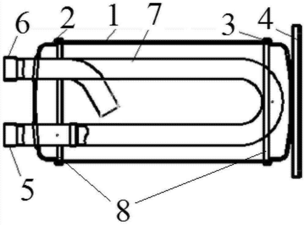
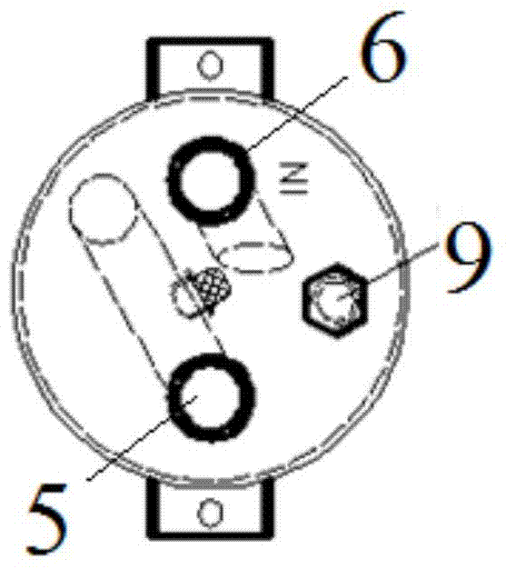
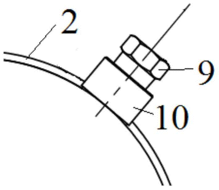
[0021] Such as Figure 1 to Figure 5 As shown, a gas-liquid separator of the present invention includes a cylinder body 1, an upper end cover 2 arranged at the upper end of the cylinder body 1, a lower end cover 3 arranged at the lower end of the cylinder body 1, a mounting plate 4, an air inlet pipe 6, and an air outlet pipe 5. U-shaped pipe 7 and screen assembly 8. The cylinder body 1 is cylindrical, with openings at both ends and a hollow interior. The lower end cover 3 is fixed on the mounting plate 4, and the mounting plate 4 is used for mounting and fixing the entire gas-liquid separator. ...


PUM


Abstract

The invention discloses a gas and liquid separator which comprises a barrel and an upper end cover arranged at the upper end of the barrel. The gas and liquid separator further comprises a pressure relief device which comprises a plug piece arranged on the upper end cover, the plug piece is provided with a vent hole for enabling an inner cavity of the gas and liquid separator and the external environment to be communicated, and the vent hole is filled with a fusible piece made of temperature control materials. After the fusible piece of the gas and liquid separator is molten, the vent hole is unblocked, the gas and liquid separator can relief pressure so that the phenomenon that the gas and liquid separator explodes due to overpressure can be avoided, and the overall system is prevented from being damaged.

Description

technical field [0001] The invention relates to a gas-liquid separator used in an air-conditioning and refrigeration system. Background technique [0002] The gas-liquid separator is generally used in air-conditioning and refrigeration systems. It uses the high-speed rotating motion of gas-liquid two-phase flow or multi-phase fluid, and is subjected to different centrifugal forces to separate liquid particles from the two-phase flow or multi-phase fluid. mechanical equipment. The main function of the gas-liquid separator is to separate the refrigerant returned from the air conditioner evaporator to the air compressor into gas and liquid refrigerant, and only return the lubricating oil in the gas and liquid refrigerant to the compressor, thereby avoiding liquid refrigerant. Refrigerant destroys the lubrication of the air compressor or damages the scroll. [0003] At present, when the gas-liquid separator is in operation, sometimes the internal air pressure will be over-pres...

Claims


Application Information

Patent Timeline
Patent Type & Authority Applications(China)
IPC IPC(8): F25B43/02
Inventor 吕文龙
Owner 芜湖三瑞香雪制冷科技有限公司
Why Eureka
Try Eureka