
A method of manufacturing an eddy current sensor probe

A technology of eddy current sensor and manufacturing method, which is applied in the direction of transmitting sensing components, instruments, scientific instruments, etc. by using electric/magnetic devices, which can solve problems such as desoldering, easy failure of glue, and coil displacement, so as to improve production and manufacturing efficiency , Reduce temperature drift performance, ensure the effect of stability

Active Publication Date: 2016-05-25
上海瑞视仪表电子有限公司
View PDF10 Cites 0 Cited by
  • Summary
  • Abstract
  • Description
  • Claims
  • Application Information

AI Technical Summary

Problems solved by technology

[0012] 1. Since the key part of the probe - between the end face of the coil and the end face of the skeleton body, is glued and fixed with 502 glue (in order to ensure that the two can be bonded in parallel during manufacture, glue with a higher concentration cannot be used) , so when the probe is used in an environment with temperature changes and vibrations for a long time, the glue that plays the role of maintaining adhesion / positioning is likely to fail, causing the coil to easily shift and loosen, resulting in the position between the end face of the coil and the end face of the component under test. changes, resulting in unstable probe operation and measurement signals becoming distorted and unreliable;
[0013] 2. Since the connection between the lead wires at both ends of the probe coil and the signal transmission cable is soldered by heating the solder wire with an electric soldering iron, when the probe is used in a temperature-changing environment for a long time with this connection method, the soldering point is prone to oxidation And desoldering, causing damage to the probe;
[0014] 3. The coil, skeleton body, protective cover and epoxy glue used for curing in the probe head body belong to four kinds of materials, and their heat resistance characteristics are completely different (different thermal expansion coefficients), and the coil and skeleton body are put into the protective cover Finally, there is only a 0.2mm gap between the inner wall of the protective cover and the outer circle of the coil and the skeleton, and there is very little epoxy glue that can penetrate. The thinly bonded epoxy glue separates, causing the coil to shift and loosen, causing the probe to work unstable or unreliable;
[0015] 4. Since there is no locking and fixing structure between the inner wall of the stainless steel shell and the front end and the skeleton body bonded to the coil, they are only filled and fixed with epoxy glue. When used in an environment of temperature, oil and vibration for a long time, stainless steel The inner wall of the shell will be separated from the epoxy glue, resulting in displacement and loosening of the probe head body, which will also cause the probe to work unstable and unreliable

Method used


Image

  • A method of manufacturing an eddy current sensor probe
  • A method of manufacturing an eddy current sensor probe
  • A method of manufacturing an eddy current sensor probe

Examples


Embodiment Construction

[0047] The present invention will be further described below in conjunction with the accompanying drawings.

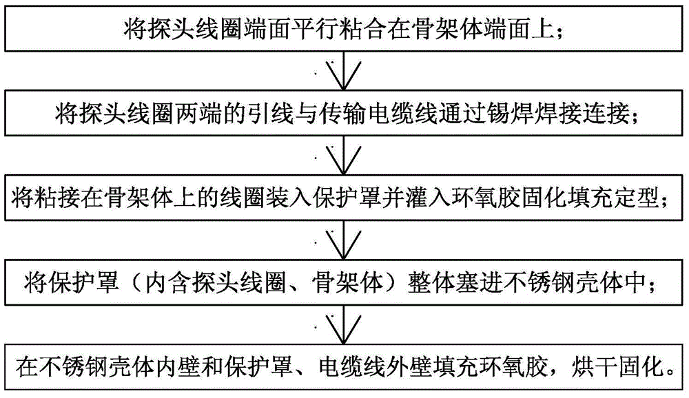
[0048] figure 1 Among them, the manufacturing steps of the existing traditional eddy current sensor probe usually include:

[0049] a. Bond the end face of the probe coil to the end face of the skeleton body in parallel;

[0050] b. Solder and connect the lead wires at both ends of the probe coil to the signal transmission cable respectively;

[0051] c. Put the coil bonded on the skeleton body into the protective cover, and pour epoxy glue into the protective cover to make it solidify and shape;

[0052] d. Put the formed probe head body into the stainless steel shell as a whole, and then pour epoxy glue into the stainless steel shell to bond and fix it. After drying, the finished product of the eddy current sensor probe can be obtained.

[0053] Its specific production process can also be used Figure 2a ~ Figure 2c shown to understand.

[0054] As already menti...


PUM


Abstract

A method for manufacturing an eddy current sensor probe belongs to the field of measuring components. It has an internal thread structure on the inner wall of the stainless steel shell, and an injection-molded locking hole structure on its head; the lead wire of the probe coil and the signal transmission cable are connected and positioned correspondingly by crimping connection technology; the probe coil and the signal transmission cable are placed Enter the injection molding machine for the first injection molding to form the probe head body with external threads; screw the finished probe head body into the stainless steel shell for the second fully sealed injection molding to form the finished probe; through two Sub-full sealing injection molding, forming a locking nail corresponding to the injection locking hole of the stainless steel shell head on the outside of the probe head body, so that the probe head body and the stainless steel shell are tightly locked and connected as one, and the probe coil is fixed and positioned There is no movement or loosening, and the expansion coefficient of the finished probe has good consistency, ensuring the stability, reliability and safety of the eddy current sensor's measurement signal under long-term working conditions.

Description

technical field [0001] The invention belongs to the field of measuring components, in particular to a manufacturing process and structure of an eddy current sensor probe. Background technique [0002] The eddy current sensor is an electrical sensor based on the principle of the eddy current effect. [0003] The eddy current sensor can realize non-contact measurement of various physical quantities whose surface is a metal conductor, such as displacement, vibration, thickness, speed, stress, hardness and other parameters. This sensor can also be used for non-destructive testing. [0004] The eddy current sensor has simple structure, wide frequency response, high sensitivity, large measurement range, strong anti-interference ability, especially the advantages of non-contact measurement, and is often used to measure the shaft displacement, shaft vibration, and shaft speed of large rotating machinery. Long-term real-time monitoring of such parameters can analyze the working cond...

Claims


Application Information

Patent Timeline
Patent Type & Authority Patents(China)
IPC IPC(8): G01D5/12G01N27/90G01N27/9093
Inventor 徐健沈慧
Owner 上海瑞视仪表电子有限公司
Learn More