Automatic sampler

A technology of automatic sample injection and container, which is applied to instruments, scientific instruments, measuring devices, etc., can solve the problems of high cost of use and maintenance, large space, occupation, etc., so as to reduce the cost of manufacturing and maintenance, and save space. Effect

Inactive Publication Date: 2014-07-02
SHIMADZU CORP
View PDF7 Cites 4 Cited by
  • Summary
  • Abstract
  • Description
  • Claims
  • Application Information

AI Technical Summary

Problems solved by technology

[0003] Generally speaking, switching valves are composed of drive control mechanisms such as motors and sensors, and actuators such as rotors and stators. The cost of use and maintenance is relatively high, and it takes up a large space

Method used


Image

  • Automatic sampler
  • Automatic sampler
  • Automatic sampler

Examples


Embodiment Construction

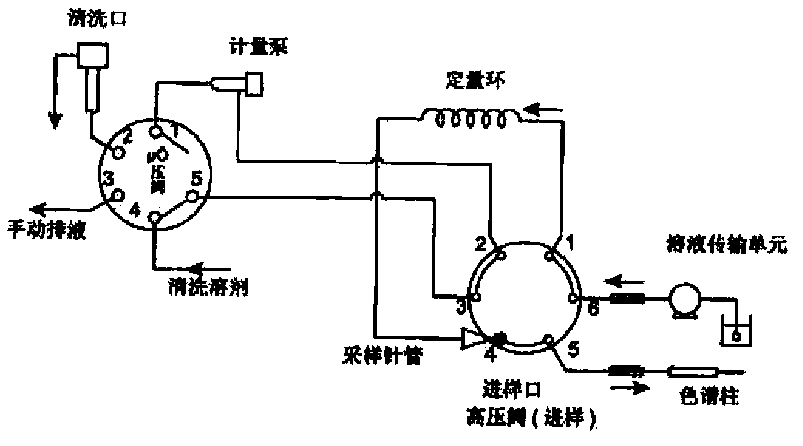
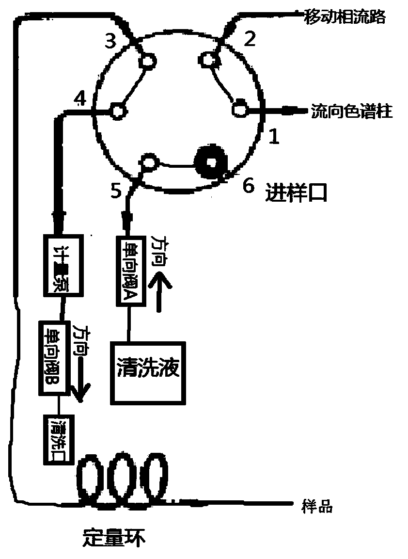
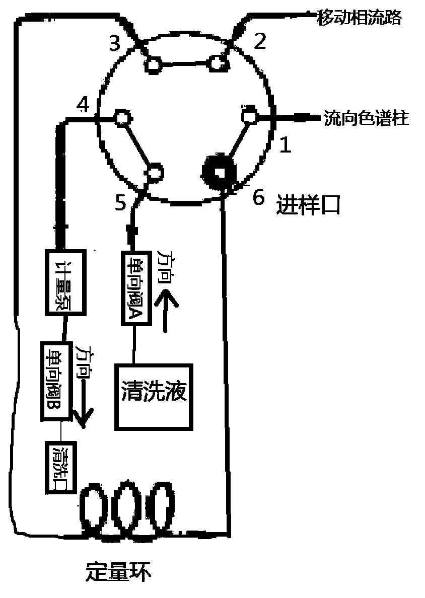
[0010] Refer to the attached Figure 2a-2d The sampling process of the autosampler according to the embodiment of the present invention will be described.

[0011] For convenience, the ports of the switching valve are numbered 1-6 in sequence. Port 1 is connected to the chromatographic column of the liquid phase analyzer, port 2 is connected to the high-pressure mobile phase flow path, port 3 is connected to the quantitative loop, port 4 is connected to the metering pump, and port 5 Connect the outlet of one-way valve A, and port 6 is the sample inlet. Such as Figure 2a As shown, at this time, ports 1 and 2, 3 and 4, and 5 and 6 of the switching valve are connected respectively, and the sampling needle is inserted into the sample bottle, and the metering pump starts to inhale. The flow direction is indicated by the arrows, from the sampling needle to the loop, through ports 3 and 4, where the metering pump draws in the sample.

[0012] Next, sample injection and delivery o...


PUM


Abstract

The invention discloses an automatic sampler which is used for guiding sucked samples into an analysis flow path of a liquid chromatographic instrument. The automatic sampler is provided with a switching valve and works through the switching of the switching valve; the automatic sampler also comprises a first one-way valve and a second one-way valve; an outlet of the first one-way valve is connected with a cleaning liquid inlet of the switching valve; the cleaning liquid inlet is communicated with a sample inlet of the switching valve or a cleaning waste liquid outlet by switching; the inlet of the first one-way valve is communicated with the cleaning liquid in a cleaning liquid container; the cleaning waste liquid outlet is connected with an inlet of a metering pump; an outlet of the metering pump is connected with an inlet of the second one-way valve.

Description

technical field [0001] The invention relates to an automatic sample injector for automatically injecting a sample into an analysis flow path of a liquid chromatograph. Background technique [0002] In the prior art, the structure of the autosampler used in the known liquid chromatograph is as follows: figure 1 As shown, it includes a high-pressure switching valve and a low-pressure switching valve, as well as sampling needles, metering pumps, quantitative loops and other components. The steps of sample suction, introduction, and cleaning are completed by switching the communication relationship between each port of the switching valve. [0003] Generally speaking, switching valves are composed of drive control mechanisms such as motors and sensors, and actuators such as rotors and stators. The cost of use and maintenance is high, and it needs to occupy a large space. Contents of the invention [0004] In order to solve the above-mentioned problems in the prior art, the pr...

Claims


Application Information

Patent Timeline
IPC IPC(8): G01N30/24
Inventor 张亮
Owner SHIMADZU CORP
Why Eureka
Try Eureka