
Single-spindle single control system applied to air covered yarn machine and control method

The technology of covering machine and air bag is applied in the field of single-spindle and single-control control system, which can solve the problems of many leaks, unable to meet the flexible production requirements of small batch, multi-variety and high-tech content of manufacturers, and low production efficiency. Achieve the effect of improving the speed of data processing, enhancing general scalability, and strong practicability

Inactive Publication Date: 2014-07-02
SOUTH CHINA UNIV OF TECH
View PDF2 Cites 3 Cited by
  • Summary
  • Abstract
  • Description
  • Claims
  • Application Information

AI Technical Summary

Problems solved by technology

[0003] 1. The control systems of the current air-covered yarn machines are all centralized control types. One machine with multiple spindles can only produce one variety with one process, which cannot meet the flexibility of small batches, multiple varieties and high-tech content of manufacturers. production requirements
[0004] 2. The production efficiency is low, the control precision is not high, and the production of fine denier yarns will have defects such as many yarn breakages, many leakages, and uneven drafting multiples.

Method used


Image

  • Single-spindle single control system applied to air covered yarn machine and control method
  • Single-spindle single control system applied to air covered yarn machine and control method
  • Single-spindle single control system applied to air covered yarn machine and control method

Examples


Embodiment

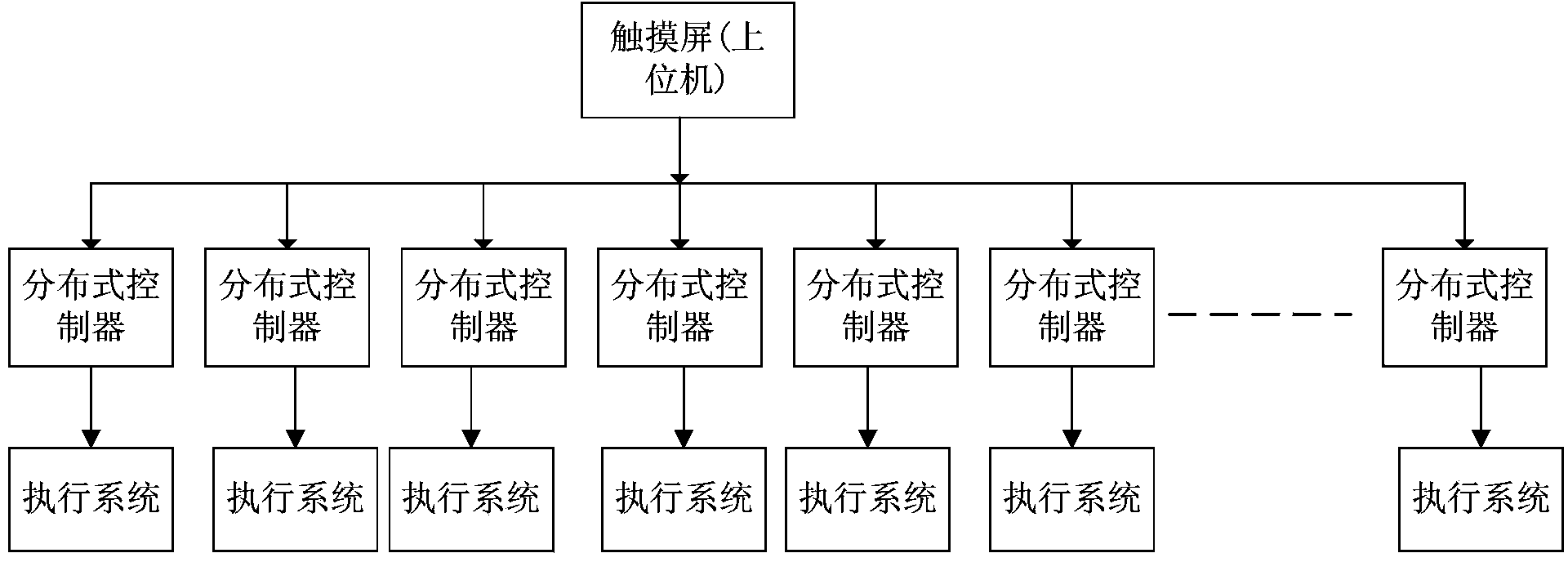
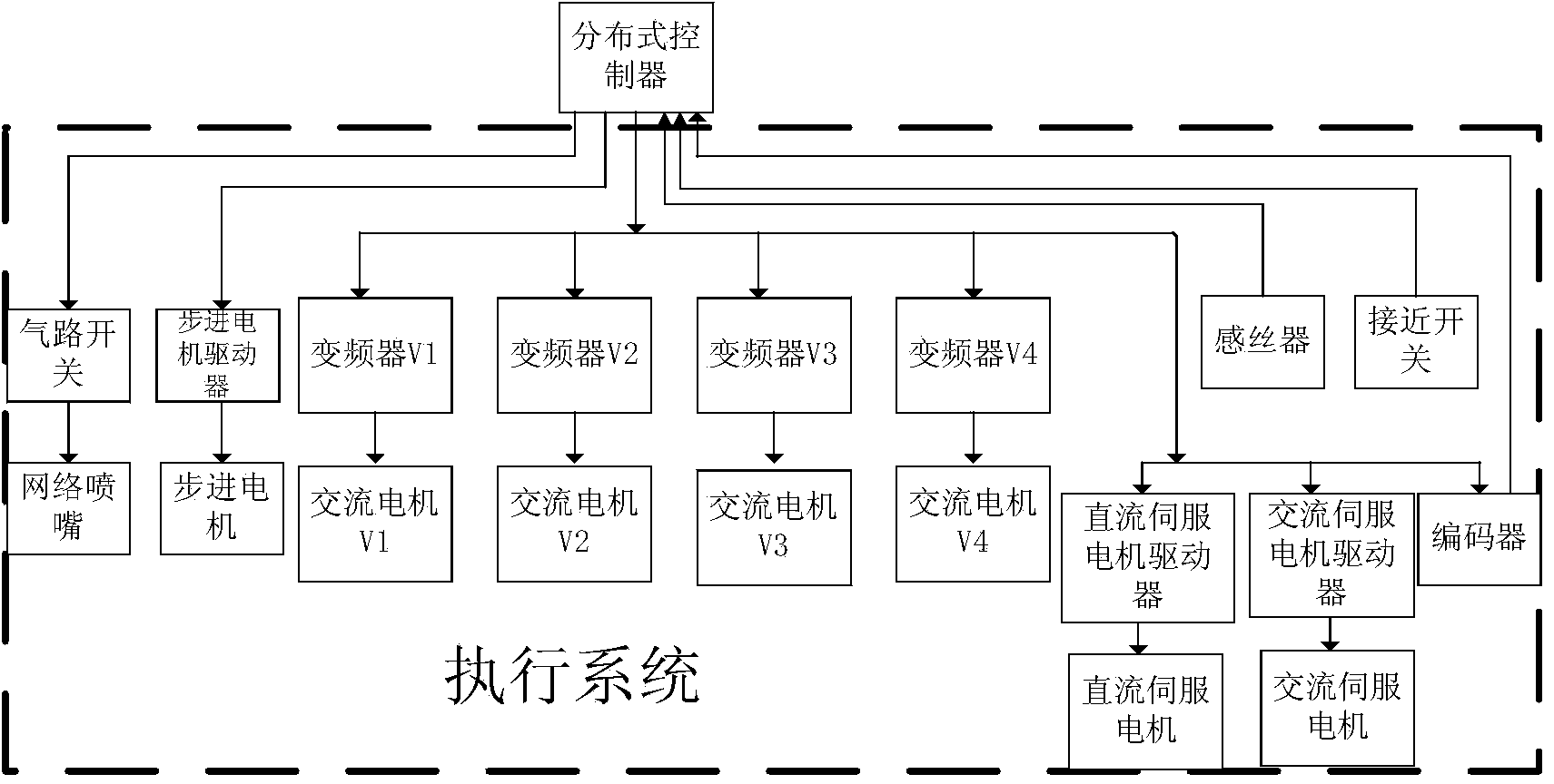
[0040] Such as figure 1 As shown, the single-spindle single-control control system of the air covering yarn machine includes a touch screen and a distributed controller. The touch screen is connected to 48 distributed controllers, and each distributed controller is connected to an executive system, such as figure 2 As shown, the execution system includes: four inverters: inverter V1, inverter V2, inverter V3, and inverter V4, four AC motors: AC motor V1, AC motor V2, AC motor V3, and AC motor V4 , A stepper motor driver, a stepper motor, an AC servo motor driver, an AC servo motor, a DC servo motor driver, a DC servo motor, a DC servo motor driver, two wire sensors, an encoder, three A proximity switch, a network nozzle and a gas circuit switch.

[0041] The touch screen is respectively connected with the distributed controller of each spindle. The distributed controller is respectively connected with four frequency converters, a stepping motor driver, an AC servo motor driver, ...


PUM


Abstract

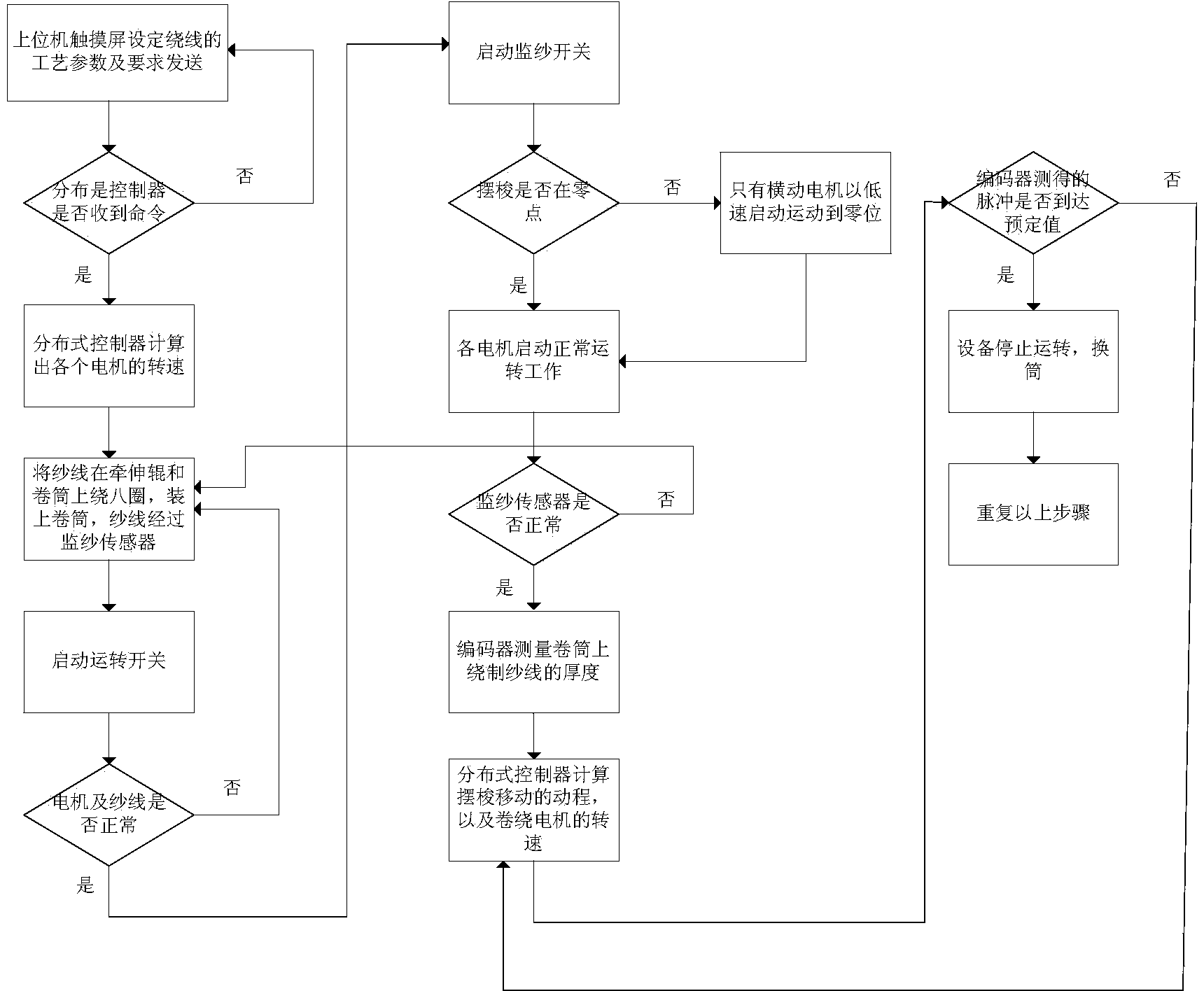
The invention discloses a single-spindle single control system applied to an air covered yarn machine. The system comprises an upper computer, a distributed controller and an execution system. The invention further discloses a control method of the single-spindle single control system applied to the air covered yarn machine. The method includes the following steps that (1) the upper computer sets process parameters and sends the process parameters to the distributed controller; (2) whether data exist is judged; (3) the rotation speed of each motor is calculated; (4) a roller is clamped on a clamping arm; (5) an operation switch is started; (6) whether the motors operate normally or whether yarn breaks is monitored; (7) a yarn monitoring switch is started; (8) whether shuttle hooks are at zero positions is judged; (9) whether a yarn monitoring sensor works normally is monitored; (10) the thickness of the yarn is calculated; (11) the stroke of the shuttle hooks and the speed of a direct-current servo motor are calculated; (12) whether the number of pulses reaches a preset value is judged; (13) the roller is replaced when the yarn is fully reeled, and the step 1 to the step 12 are repeated. The system and the method have the advantages of being high in precision, high in production efficiency and the like.

Description

Technical field [0001] The invention relates to an air covering yarn machine technology in the textile industry, in particular to a single spindle single control control system and a control method applied to the air covering yarn machine. Background technique [0002] The air covering yarn machine is a yarn processing machine. It combines the spandex delivered from the spandex feeding device with the untwisted filament (nylon / polyester DTY) through the air covering device in the compressed air with a certain draft ratio. Under the action of network wrapping, two or more fibers with different physical properties are intertwined to form a yarn-air covered yarn. Most of the existing domestic air covering yarn machines are made by adding a simple spandex conveying device and a network nozzle device to an ordinary winder. The cost is low, and it is troublesome to change the product variety and change the process. Due to the limitation of structure and function, it can only Low-effic...

Claims


Application Information

Patent Timeline
IPC IPC(8): G05B19/418
CPCY02P90/02
Inventor 张铁罗业才邹焱飚
Owner SOUTH CHINA UNIV OF TECH
Learn More