
Root extending segment appearance parameterization design method of turbine air-cooling moving blade

A technology of shape parameters and design methods, applied in the direction of calculation, electrical digital data processing, special data processing applications, etc., to achieve the effect of scientific and reasonable shape design of root extension

Inactive Publication Date: 2014-07-02
NORTHWESTERN POLYTECHNICAL UNIV
View PDF2 Cites 8 Cited by
  • Summary
  • Abstract
  • Description
  • Claims
  • Application Information

AI Technical Summary

Problems solved by technology

[0005] The purpose of the present invention is to propose a parametric design method for the shape of the root extension section of the turbine air-cooled moving blade in view of the current situation of insufficient research on the shape of the root extension of the existing blade. Curve operations such as edges and other curves are used to construct parametric root profile section line groups, and then stretched to obtain the auxiliary geometry required in the process of constructing the root profile, and then create a bridge curve group, and constrain the bridge curve group to ensure that it is consistent with the auxiliary geometry shape at the same time The curved surface and the plane G1 on both sides of the shape of the tenon are continuous; use the skinning method and the boundary control method to obtain the shape surface of the root shape, and ensure that the shape surface of the longitudinal part is continuous with the auxiliary geometry and the surface G1 of the tenon shape; finally, the closed space surface group Converted to a solid body to get the final root shape

Method used


Image

  • Root extending segment appearance parameterization design method of turbine air-cooling moving blade
  • Root extending segment appearance parameterization design method of turbine air-cooling moving blade
  • Root extending segment appearance parameterization design method of turbine air-cooling moving blade

Examples


Embodiment Construction

[0039] This embodiment takes the parametric design process of a certain type of blade root shape as an example, and the CAD software design environment of this example is NX7.5 software.

[0040] Step 1: Create a parametric set of outrigger profile lines:

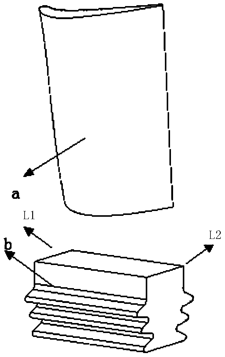
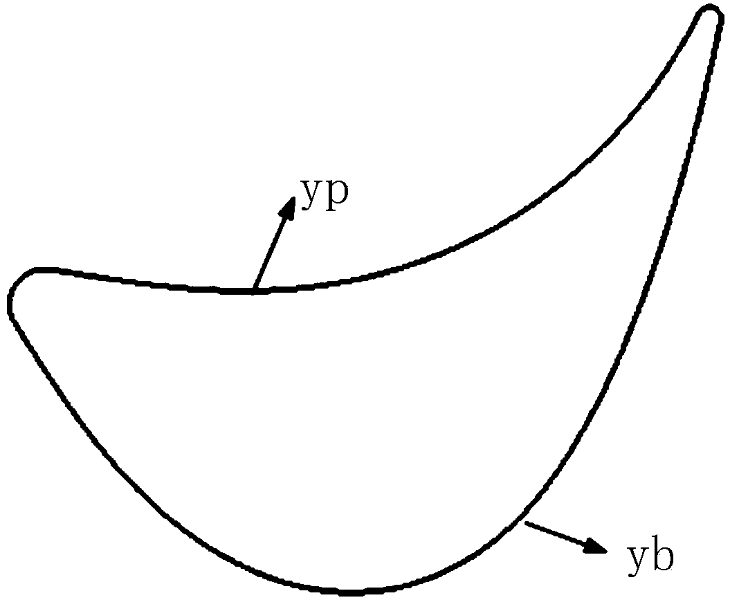
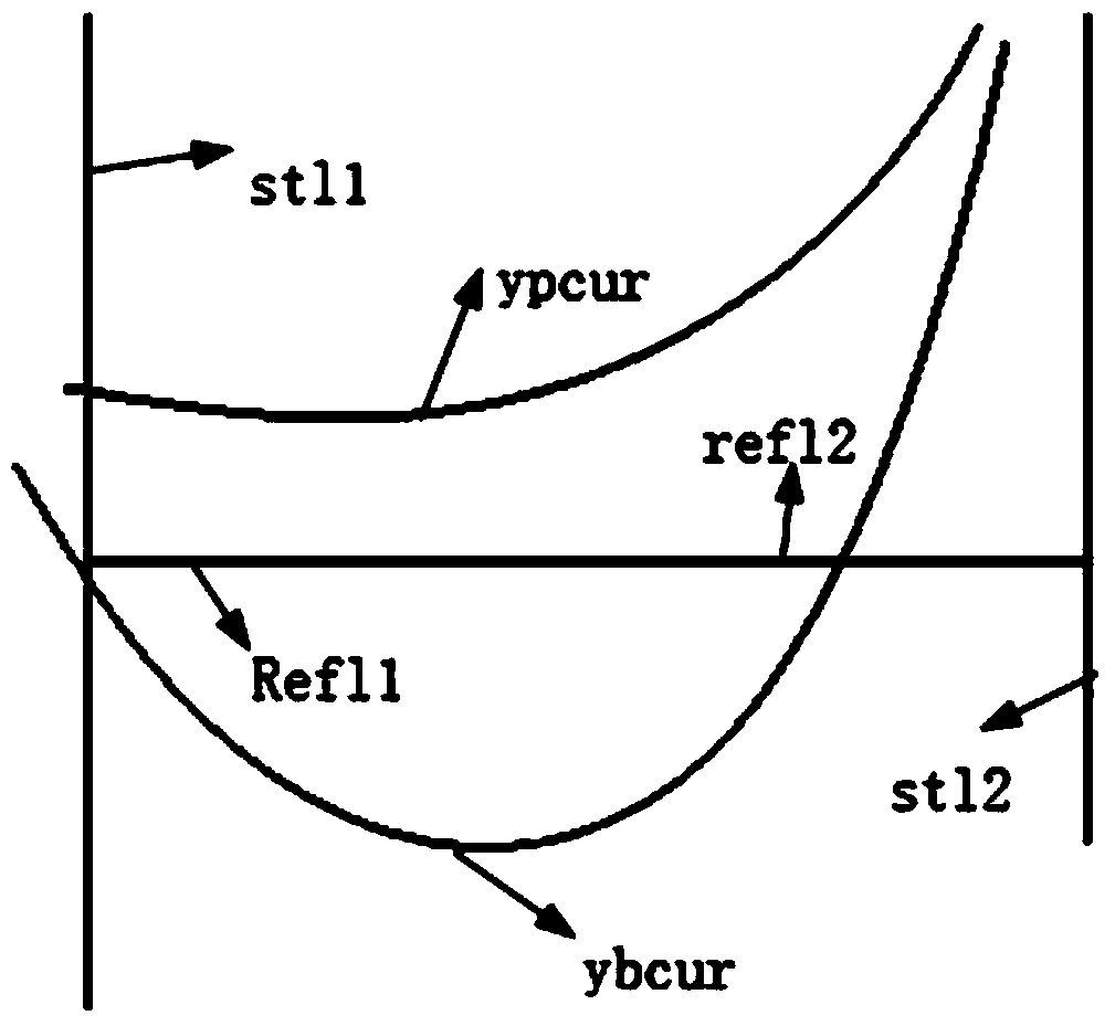
[0041] Step 1.1: Import the blade shape model and tenon shape model into the 3D modeling software; the blade shape model is a spatial entity generated by the blade shape section line through the skin method, and the blade body shape section line is the aerodynamic data point A continuous high-order curve formed by spline curve fitting. The profile line of the blade body is divided into four sections: the blade basin curve, the blade back curve, the leading edge curve and the trailing edge curve; the tenon shape model is a space entity formed by section stretching , where the top section of the tenon shape model is a regular rectangle, L1 is the starting edge of the top section of the tenon shape model in the stretching proc...


PUM


Abstract

The invention provides a root extending segment appearance parameterization design method of a turbine air-cooling moving blade. A root extending segment appearance section line set capable of being parameterized is built, an auxiliary geometry body is acquired, a bridging curve is built, the free-form surface of the root extension segment appearance is acquired through the covering method, other planes of the root extending segment appearance are acquired through the boundary control method, a formed sealed root extending segment appearance curve body is converted to an entity, and a final root extending segment appearance entity is acquired. Through the method, the complex root extending segment appearance modeling problem is converted to a plurality of problems of surface modeling, the auxiliary geology body is built, and the continuity of the root extending segment appearance curve and a tenon appearance curve on the boundary G1 is achieved accordingly; because root extending segment appearance section lines capable of being parameterized are built, the root extending segment appearance is more scientific and reasonable in design, and the method can be better applied to the engineering design field.

Description

technical field [0001] The invention relates to the field of shape design of a root section of a turbine air-cooled moving blade, in particular to a parametric design method for the shape of a root section of a turbine air-cooled moving blade. Background technique [0002] Aeroengine blades are the key components of aeroengines, which have the characteristics of complex structure, many varieties, large quantities, great influence on engine performance, and long design and manufacturing cycle. Among the aeroengine blades, the turbine moving blades with air-cooling structure are the most complex. In addition to the complex inner cavity structure, there is also a section of root structure between the edge plate and the tenon. It is a very complicated and cumbersome process to comprehensively consider factors such as inner cavity air flow, strength, turbine disk and tenon structure, and blade weight in the design of the root section structure. [0003] Relevant domestic personn...

Claims


Application Information

Patent Timeline
IPC IPC(8): G06F17/50
Inventor 李璐莫蓉覃琨万能马峰
Owner NORTHWESTERN POLYTECHNICAL UNIV
Learn More