
Installation mechanism, security and protection monitoring device and security and protection monitoring system

An installation mechanism and security monitoring technology, which is applied in the field of security monitoring systems and security monitoring devices, can solve problems such as small application range, inapplicability to independent objects, and inflexible installation methods, so as to achieve expanded application range, flexible installation methods, and security effect of effectiveness

Active Publication Date: 2014-07-02
SHENZHEN MAKTIN TECH
View PDF6 Cites 3 Cited by
  • Summary
  • Abstract
  • Description
  • Claims
  • Application Information

AI Technical Summary

Problems solved by technology

However, since the magnet body and the door magnetic host must be installed in two relatively separated positions to achieve security alarms, there are the following disadvantages: the installation method is not flexible; it is not suitable for monitoring an independent object, and the scope of application is small; the door sensor is used for glass When the window is opened, the alarm can only be triggered when the glass window changes from the closed state to the open state. If the glass window itself is in the open state, security monitoring cannot be realized when it is opened illegally.

Method used


Image

  • Installation mechanism, security and protection monitoring device and security and protection monitoring system
  • Installation mechanism, security and protection monitoring device and security and protection monitoring system
  • Installation mechanism, security and protection monitoring device and security and protection monitoring system

Examples


Embodiment 1

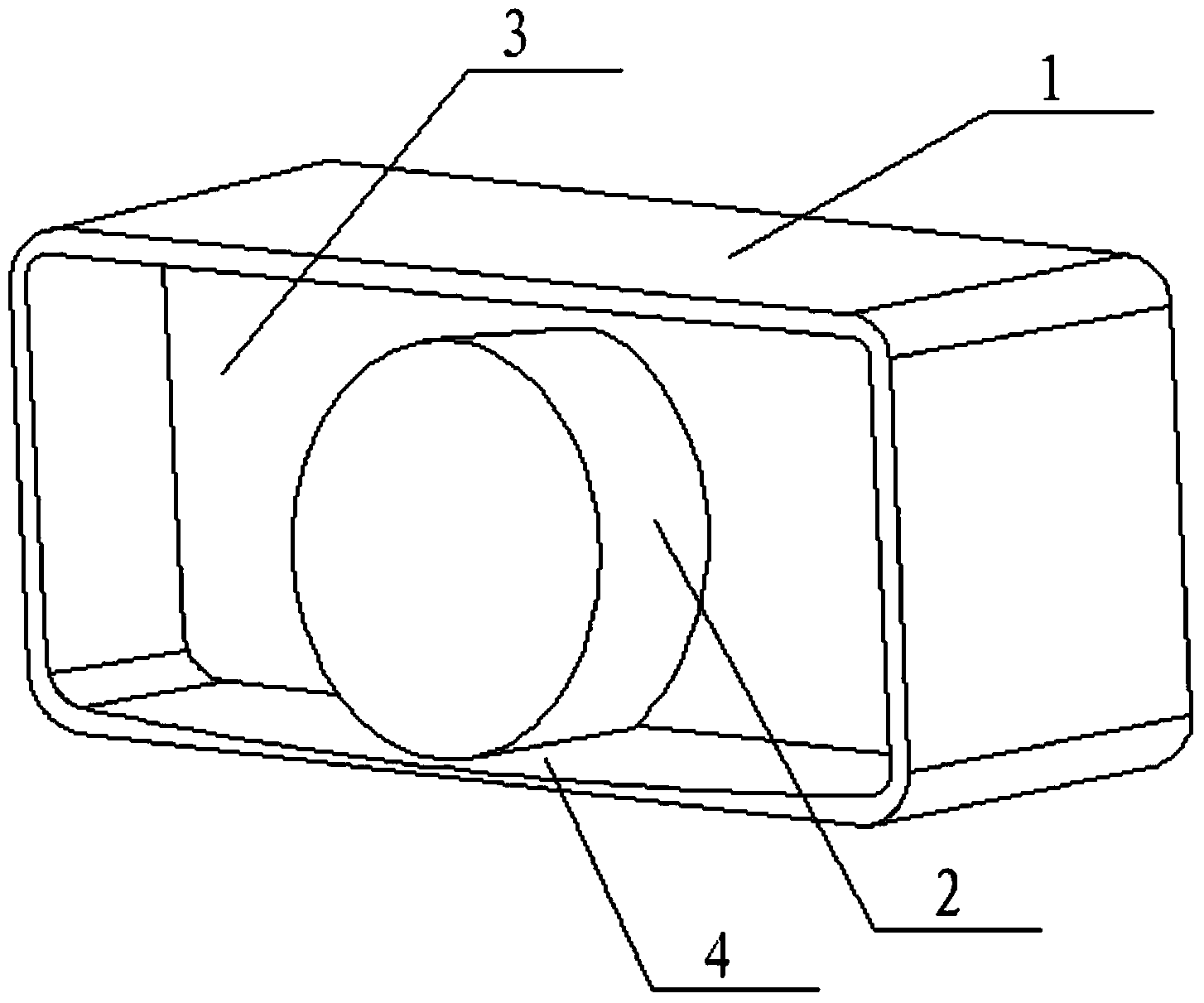
[0025] see figure 2 The installation mechanism provided in this embodiment includes a first housing 1 and a second housing 2, the first housing 1 is provided with a first cavity 3, and the second housing 2 is movably arranged on the first housing 1 of the first housing 1. In a cavity 3, the second housing 2 can roll in the first cavity 3, and the second housing 2 is provided with a second cavity (not shown in the figure) for installing a displacement detection component. In this embodiment, the second housing 2 is a cylindrical housing, and the first cavity 3 on the first housing 1 is a rectangular cavity, and the bottom wall of the rectangular cavity is provided with an arc-shaped slide with a low center and high ends. Slot 4, the purpose of setting the arc-shaped chute 4 is to facilitate the installation of the second housing 2 in the middle of the arc-shaped chute 4 in a stable state. The height of the second housing 2 is less than or equal to the height of the first cavi...

Embodiment 2

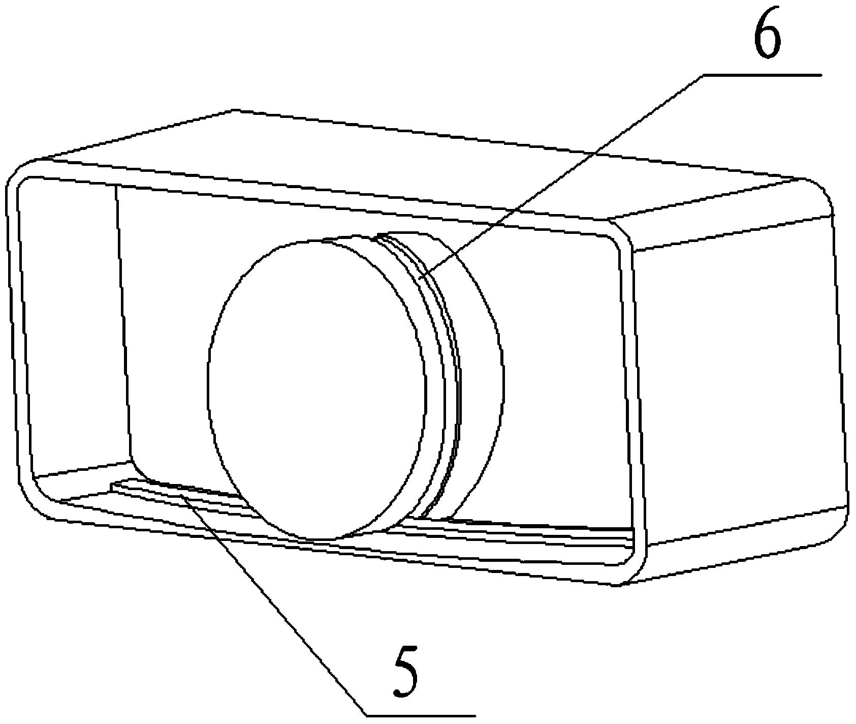
[0028] Such as image 3 As shown, this embodiment provides another structure of the installation mechanism, the structure of the installation mechanism provided by this embodiment is basically the same as the installation mechanism provided by Embodiment 1, the only difference is that the second structure of the installation mechanism provided by this embodiment The shell 2 is provided with an arc-shaped groove 6, and the bottom wall of the first cavity 3 of the first shell 1 is provided with a raised bar 5, and the arc-shaped groove 6 on the second shell 2 is in line with the first The convex strip 5 on the bottom wall of the cavity 3 is suitable. The purpose of providing the raised lines and the arc-shaped grooves is to ensure that the second housing will not roll out of the first cavity when it rolls on the bottom wall of the first cavity. Of course, there can be two or more convex lines and grooves. Of course, arc-shaped grooves can also be provided on the second housing...


PUM


Abstract

The invention relates to the technical field of security and protection, in particular to an installation mechanism, a security and protection monitoring device and a security and protection monitoring system. The installation mechanism is used for installing a displacement detection part, and comprises a first shell (1) and a second shell (2), a first cavity (3) is arranged in the first shell (1), the second shell (2) can arranged in the first cavity (3) of the first shell (1) in a sliding mode, and a second cavity used for installing the displacement detection part is arranged in the second shell (2). According to the installation mechanism, the second shell is driven to slide or roll in the first cavity due to slight moving of the first shell, and displacement detection can be achieved after the displacement detection part is disposed in the second shell. Displacement detection can be achieved as long as the installation mechanism is arranged on an independent monitored object, and accordingly the problem that traditional door sensors have to be installed on two opposite and separated positions to achieve displacement detection is solved.

Description

technical field [0001] The invention relates to the field of security technology, in particular to an installation mechanism for installing a security monitoring device, a security monitoring device and a security monitoring system using the installation mechanism. Background technique [0002] At present, the door sensor is the most commonly used security monitoring device. The door sensor includes a door sensor host (main controller) and a magnet body. Such as figure 1 As shown, the magnet body 10 and the door magnet host 20 are installed on the door frame 30 and the door body 40 respectively. When the door is closed, the position of the magnet body and the door sensor host is fixed, and the door sensor is in a stable state; when the door is opened, the magnet body is far away from the door sensor host, triggering an alarm and realizing security monitoring. However, since the magnet body and the door magnetic host must be installed in two relatively separated positions t...

Claims


Application Information

Patent Timeline
IPC IPC(8): G08B13/02G08B13/08
Inventor 吴晓舟
Owner SHENZHEN MAKTIN TECH
Features
  • Generate Ideas
  • Intellectual Property
  • Life Sciences
  • Materials
  • Tech Scout
  • Unparalleled Data Quality
  • Higher Quality Content
  • 60% Fewer Hallucinations
Learn More