Ultra-wideband cavity-backed bow-tie antenna device for ground penetrating radar

A technology of bow-tie antenna and ground penetrating radar, which is applied in the field of earth detection, can solve the problems of not being able to share a trailer, not being able to realize grounding measurement of the radiation surface of the antenna, and not being able to realize walking measurement of the radiation surface of the antenna, so as to reduce frictional resistance, cost-saving effect

Inactive Publication Date: 2014-07-02
NORTHEAST INST OF GEOGRAPHY & AGRIECOLOGY C A S
View PDF5 Cites 3 Cited by
  • Summary
  • Abstract
  • Description
  • Claims
  • Application Information

AI Technical Summary

Problems solved by technology

[0003] In order to solve the problem that two cavity-backed bow tie antennas with a 3dB bandwidth of 50MHz to 300MHz and a 3dB bandwidth of about 300MHz to 1GHz in the prior art cannot share a trailer, the invention cannot realize walking measurement with adjustable height of the antenna radiation surface from the ground, and The problem that the grounding measurement of the radiation surface of the antenna cannot be realized, and then a ground-penetrating radar ultra-wideband cavity-backed bow-tie antenna device is provided

Method used


Image

  • Ultra-wideband cavity-backed bow-tie antenna device for ground penetrating radar
  • Ultra-wideband cavity-backed bow-tie antenna device for ground penetrating radar
  • Ultra-wideband cavity-backed bow-tie antenna device for ground penetrating radar

Examples


specific Embodiment approach 1

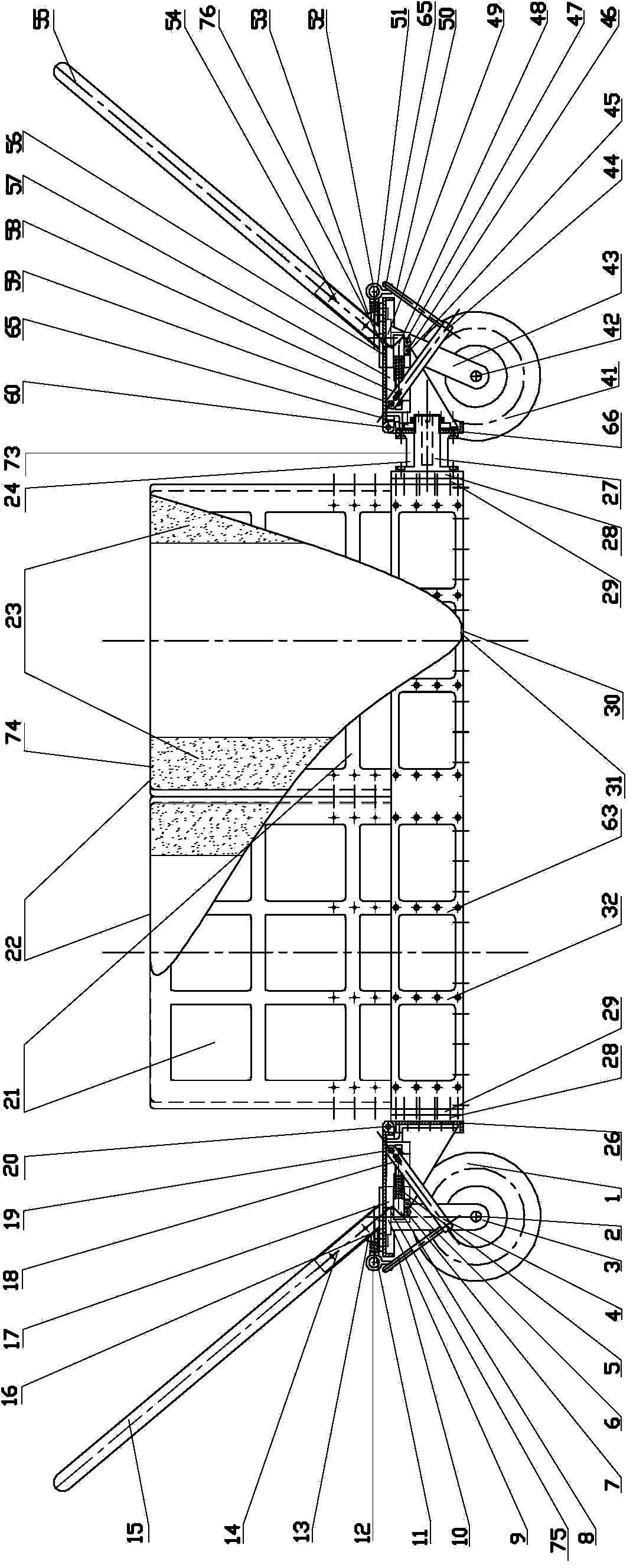
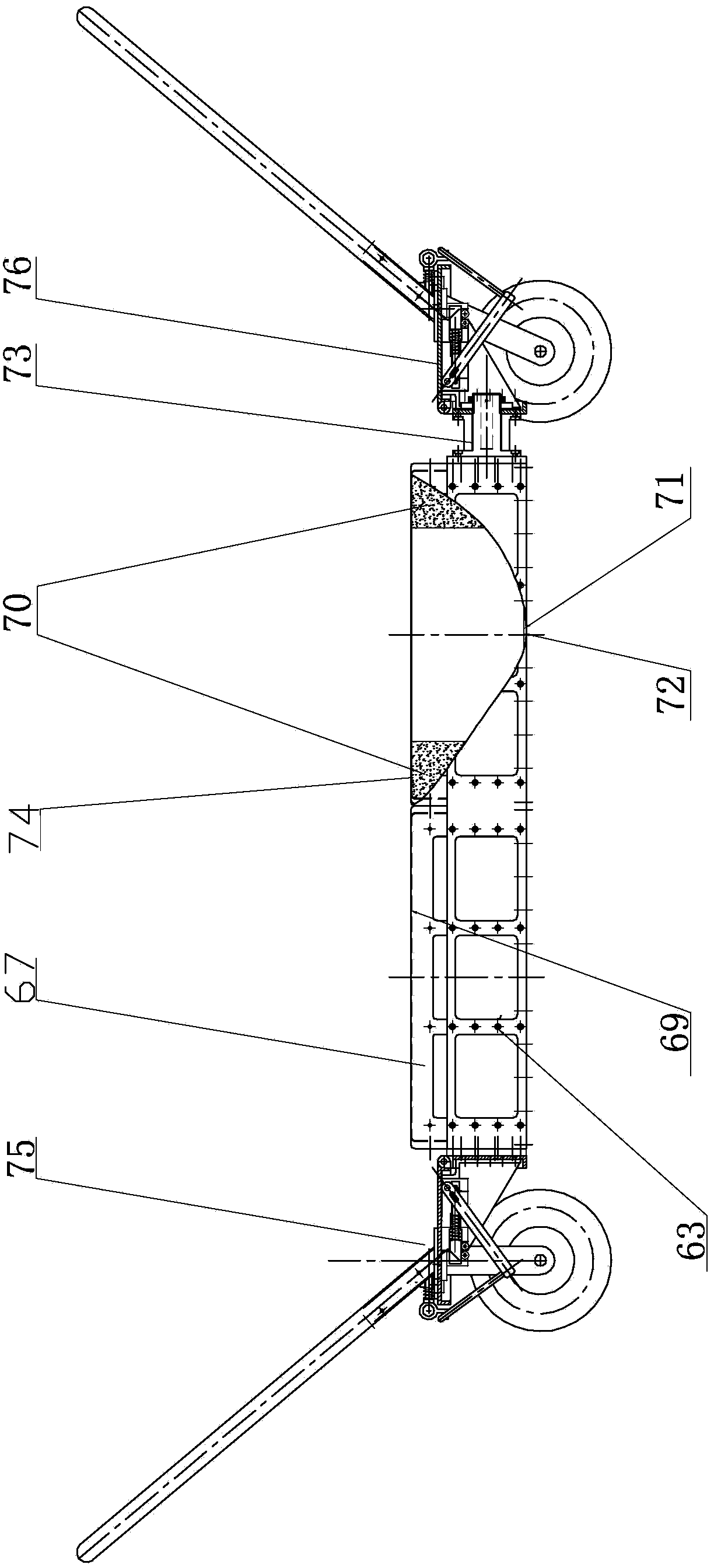
[0007] Specific implementation mode one: combine Figure 1-Figure 17 Describe this embodiment, a ground-penetrating radar ultra-wideband cavity-backed bowtie antenna device described in this embodiment, the device includes a cavity-backed bowtie antenna 74, a first controllable landing public trailer 75, a second controllable landing public Trailer 76 and public frame 63, a first controllable drop public trailer 75 is installed on one side of public frame 63, and the opposite side with first controllable drop public trailer 75 is installed with second controllable drop on the public frame 63 The public trailer 76 and the cavity-backed bow-tie antenna 74 are fixedly mounted on the public frame 63 through screw connections.

specific Embodiment approach 2

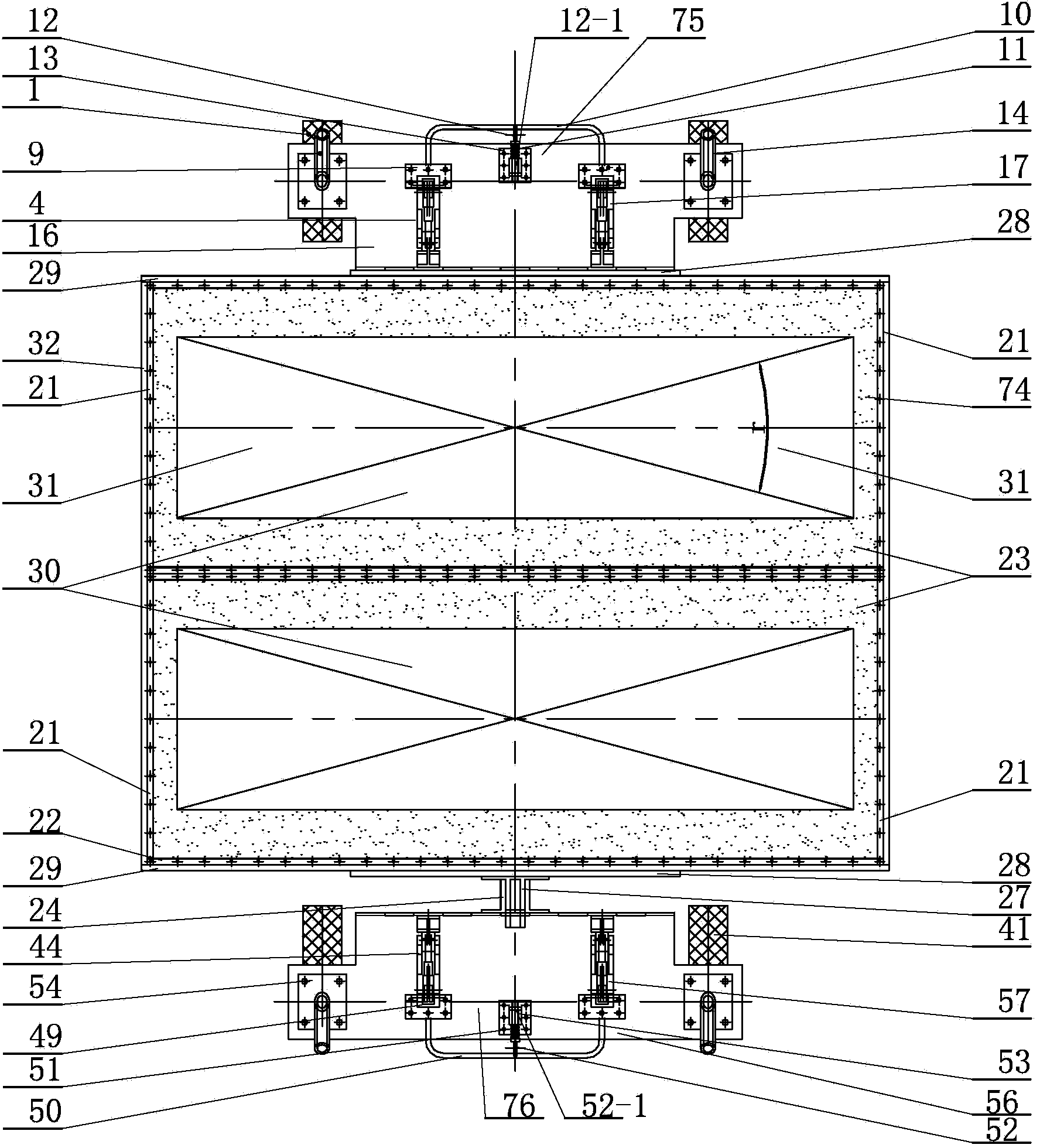
[0008] Specific implementation mode two: combination Figure 1-Figure 4 Describe this embodiment mode, a ground penetrating radar ultra-wideband cavity-backed bow-tie antenna device described in this embodiment mode, the common frame 63 includes two first balanced transition bridges 28, two second balanced transition bridges 29 and two Public bridge 32, the first balanced transition bridge 28, the second balanced transition bridge 29 and public bridge 32 are rectangular plates, the side of each first balanced transition bridge 28 is fixedly connected with the side of a second balanced transition bridge 29, the back The two ends of the cavity bow tie antenna are respectively fixedly connected to one side of a second balanced transition bridge 29, and one end of each second balanced transition bridge 29 is fixedly connected to one end of another second balanced transition bridge 29 through a common bridge 32 , the other side of one of the first balance transition bridges 28 is f...

specific Embodiment approach 3

[0009] Specific implementation mode three: combination figure 1 , image 3 , Figure 5 , Figure 10-Figure 13. Describe this embodiment, a ground-penetrating radar ultra-broadband cavity-backed bow-tie antenna device described in this embodiment, the first controllable landing public trailer 75 includes a first U-shaped landing handle 10, a first lock hole Pin spring 11, the first lock pull hole pin 12, the first lock pull hole pin holder 13, the first U-shaped drag bar 15, the first horizontal plate 16, the first fixed pin shaft 20, the first vertical plate 26, two One first trailer wheel 1, two first trailer axles 2, two fixed wheel support frames 3, two first unlocking transmission handles 4, two first deadbolt springs 5, two first deadbolt linkage rods 8 , two first lock card hole seats 9, two first lock pull hole pin fixing nuts 12-1, two first drag bar fixing seats 14, two first support lock frames 17, two first linkage shafts 18. Two first fixed lock shafts 19, four...


PUM


Abstract

The invention relates to a bow-tie antenna device, in particular to an ultra-wideband cavity-backed bow-tie antenna device for a ground penetrating radar, and aims to solve the problems that in the prior art, a cavity-backed bow-tie antenna with the 3dB bandwidth ranging from 50 MHz to 300 MHz and a cavity-backed bow-tie antenna with the 3dB bandwidth ranging from 300 MHz to1 GHz cannot share one type of trailers, walking measurement with the height of an antenna radiating surface away from the ground cannot be achieved in an adjustable mode, and grounding measurement of the antenna radiating surface cannot be achieved. The device comprises a cavity-backed bow-tie antenna, a first common trailer with landing controllable, a second common trailer with landing controllable and a common frame, wherein the first common trailer with landing controllable is installed on one side of the common frame, the second common trailer with landing controllable is arranged on the other side, opposite to the first common trailer with landing controllable, of the common frame, and the cavity-backed bow-tie antenna is fixedly installed on the common frame through threaded connection. The ultra-wideband cavity-backed bow-tie antenna device belongs to the field of earth probing.

Description

technical field [0001] The invention relates to a bow-tie antenna device, in particular to a ground-penetrating radar ultra-wideband cavity-backed bow-tie antenna device, which belongs to the technical field of earth detection. Background technique [0002] In order to transmit and receive radar signals with ultra-wideband spectrum efficiently and without distortion, the receiving and transmitting antennas of the ground penetrating radar system must have good ultra-wideband performance. Distributed loading cavity-backed bowtie antennas can suppress unnecessary radiation fields, and at the same time reduce the influence of the surrounding environment and metal parts and electronic components in the system on the antenna radiation performance, so the shielded cavity-backed bowtie antennas whose inner walls are covered with absorbing materials Be the first choice. Normally, according to the triangular bow tie antenna theory, the 3dB bandwidth is about 50MHz~300MHz when the cen...

Claims


Application Information

Patent Timeline
Patent Type & Authority Applications(China)
IPC IPC(8): H01Q1/12G01S7/03
Inventor 刘宝江董航
Owner NORTHEAST INST OF GEOGRAPHY & AGRIECOLOGY C A S
Why Eureka
Try Eureka