A ground-penetrating radar ultra-wideband cavity-backed bow-tie antenna device
A bow-tie antenna and ground penetrating radar technology, applied in the field of earth detection, can solve the problems of not being able to share a trailer, unable to realize the grounding measurement of the radiation surface of the antenna, unable to realize the walking measurement of the antenna radiation surface, etc., to reduce friction resistance, cost-saving effect
- Summary
- Abstract
- Description
- Claims
- Application Information
AI Technical Summary
Problems solved by technology
Method used
Image
Examples
specific Embodiment approach 1
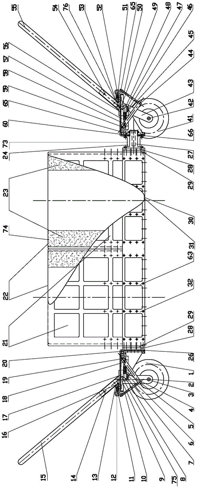
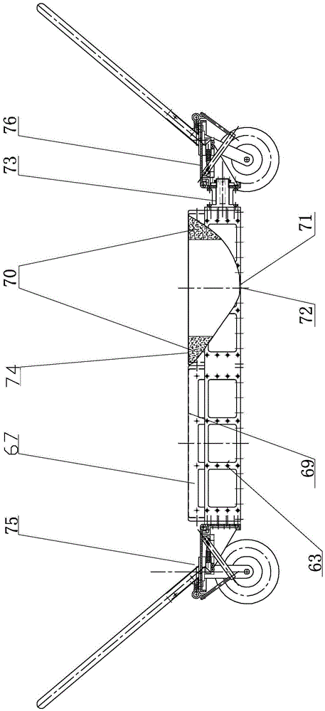
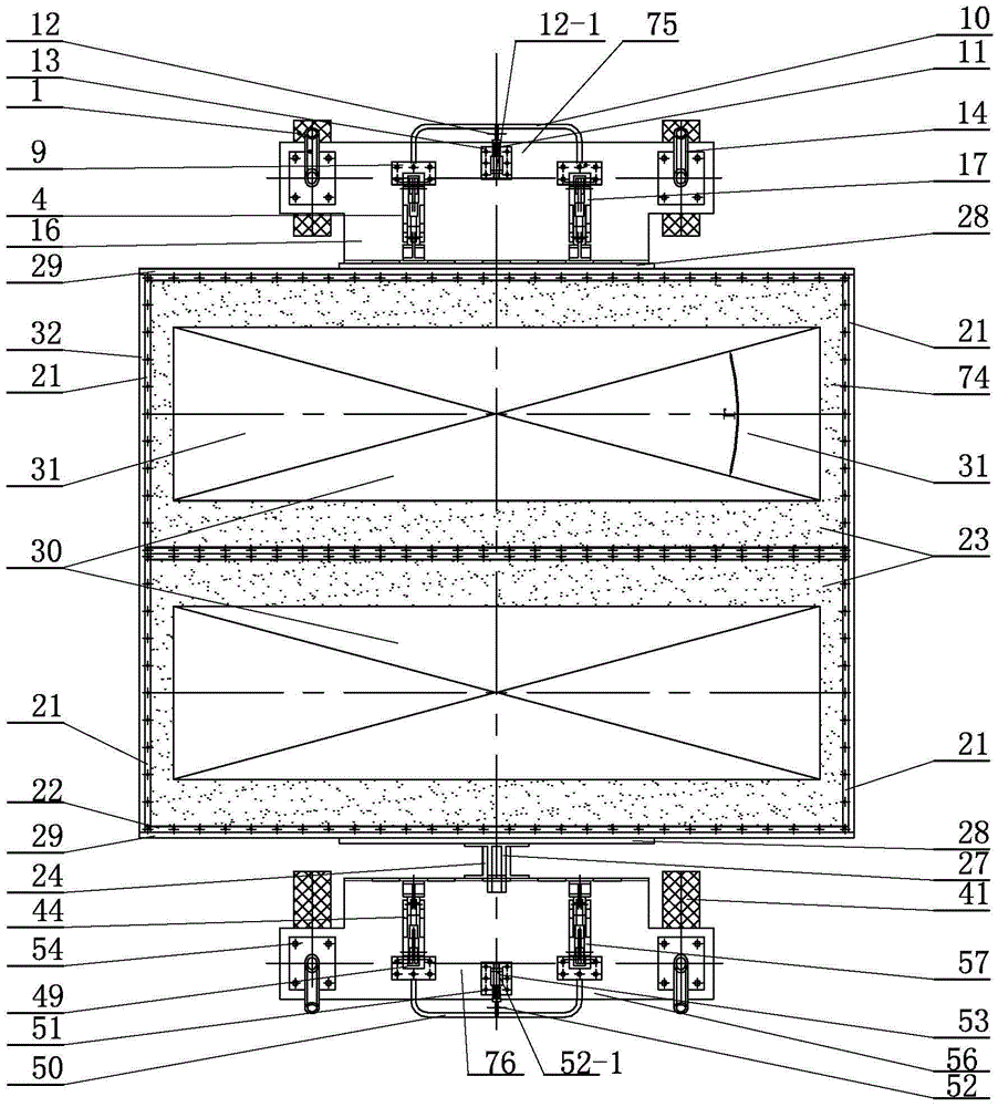
[0007] Specific implementation mode one: combine Figure 1-Figure 17 Describe this embodiment, a ground-penetrating radar ultra-wideband cavity-backed bowtie antenna device described in this embodiment, the device includes a cavity-backed bowtie antenna 74, a first controllable landing public trailer 75, a second controllable landing public Trailer 76 and public frame 63, the first controllable drop public trailer 75 is installed on one side of public frame 63, and the opposite side with the first controllable drop public trailer 75 is installed with the second controllable drop public trailer 75 on the public frame 63. The trailer 76 and the cavity-backed bow-tie antenna 74 are fixedly mounted on the common frame 63 through screw connections.
specific Embodiment approach 2
[0008] Specific implementation mode two: combination Figure 1-Figure 4 Describe this embodiment mode, a ground penetrating radar ultra-wideband cavity-backed bow-tie antenna device described in this embodiment mode, the common frame 63 includes two first balanced transition bridges 28, two second balanced transition bridges 29 and two Public bridge 32, the first balanced transition bridge 28, the second balanced transition bridge 29 and public bridge 32 are rectangular plates, and one side of a first balanced transition bridge 28 is fixedly connected with a side of a second balanced transition bridge 29, One side of another first balanced transition bridge 28 is fixedly connected with a side of another second balanced transition bridge 29, and one end of the cavity-backed bow-tie antenna 74 is fixedly connected with a side of a second balanced transition bridge 29, and the cavity-back The other end of the bow-tie antenna 74 is fixedly connected to one side of another second b...
specific Embodiment approach 3
[0009] Specific implementation mode three: combination figure 1 , image 3 , Figure 5 , Figure 10-Figure 13. Describe this embodiment, a ground-penetrating radar ultra-broadband cavity-backed bow-tie antenna device described in this embodiment, the first controllable landing public trailer 75 includes a first U-shaped landing handle 10, a first lock hole Pin spring 11, the first lock pull hole pin 12, the first lock pull hole pin holder 13, the first U-shaped drag bar 15, the first horizontal plate 16, the first fixed pin shaft 20, the first vertical plate 26, two One first trailer wheel 1, two first trailer axles 2, two fixed wheel support frames 3, two first unlocking transmission handles 4, two first deadbolt springs 5, two first deadbolt linkage rods 8 , two first lock card hole seats 9, two first lock pull hole pin fixing nuts 12-1, two first drag bar fixing seats 14, two first support lock frames 17, two first linkage shafts 18. Two first fixed lock shafts 19, four...
PUM
 Abstract
Description
Claims
Application Information
 - R&D
- Intellectual Property
- Life Sciences
- Materials
- Tech Scout
- Unparalleled Data Quality
- Higher Quality Content
- 60% Fewer Hallucinations
Browse by: Latest US Patents, China's latest patents, Technical Efficacy Thesaurus, Application Domain, Technology Topic, Popular Technical Reports.
© 2025 PatSnap. All rights reserved.Legal|Privacy policy|Modern Slavery Act Transparency Statement|Sitemap|About US| Contact US: help@patsnap.com


