Multi-band antenna

A multi-frequency antenna and radio frequency signal technology, applied in antennas, resonant antennas, slot antennas, etc., can solve the problems of compressed antenna headroom area, electronic device mechanism and appearance design can not break through, and achieve the effect of reducing headroom area

Inactive Publication Date: 2014-07-02
COMPAL ELECTRONICS INC
View PDF3 Cites 20 Cited by
  • Summary
  • Abstract
  • Description
  • Claims
  • Application Information

AI Technical Summary

Problems solved by technology

However, the appearance design with metal texture compresses the headroom area required by the antenna, which leads to the problem that the electronic device cannot break through the current situation in terms of mechanism and appearance design.

Method used


Image

  • Multi-band antenna
  • Multi-band antenna
  • Multi-band antenna

Examples


Embodiment Construction

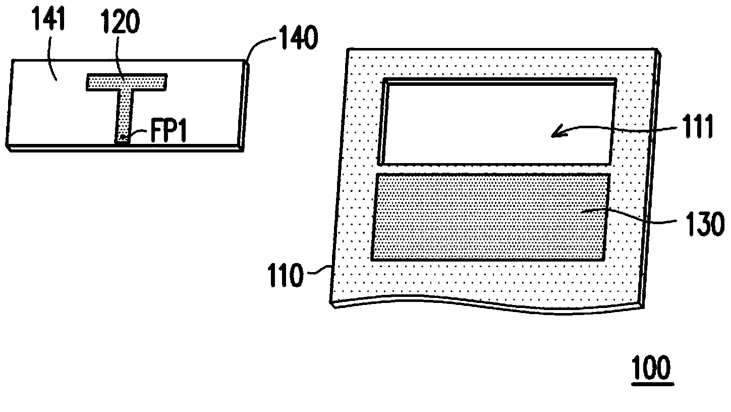
[0031] figure 1 It is an exploded view of a multi-frequency antenna according to an embodiment of the present invention. refer to figure 1 , the multi-frequency antenna 100 includes a metal plate 110 , a radiator 120 , a ground plane 130 and a substrate 140 . Wherein, the metal plate 110 has a slot 111 , and the slot 111 passes through the metal plate 110 . In addition, the metal plate 110 is electrically connected to the ground plane 130 . For example, in figure 1 In an embodiment, the ground plane 130 is directly attached to the metal plate 110 so that the metal plate 110 is electrically connected to the ground plane 130 .

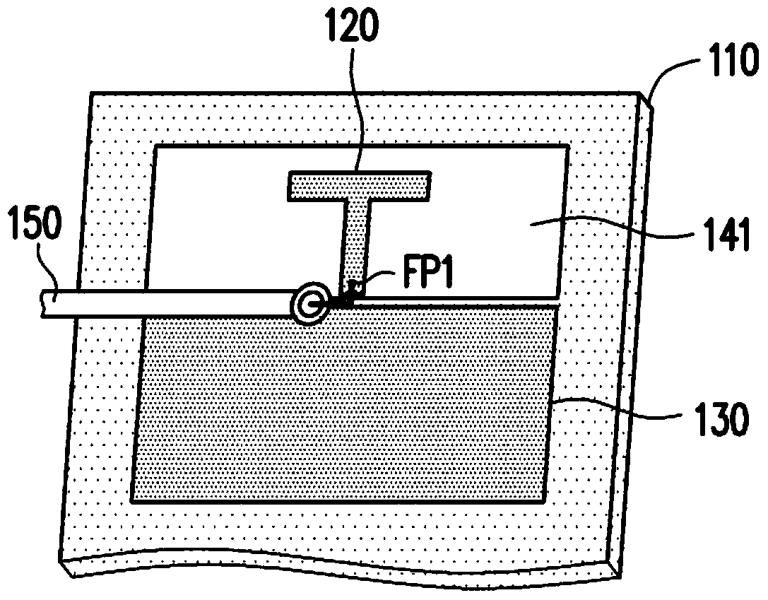
[0032] In addition, in the overall configuration, the size of the substrate 140 is set according to the size of the slot 111 of the metal plate 110 , so the substrate 140 can be embedded into the slot 111 . In addition, the radiation element 120 is disposed on a surface 141 of the substrate 140 . In this way, the radiation element 120 will be locat...


PUM


Abstract

A multi-band antenna including a metal plate and a radiation element is provided. The metal plate is electrically connected to a ground plane and has a slot. A resonant path is formed by the edges of the slot. The radiation element has a feeding point and is located in the slot of the metal plate. A feeding signal from the radiation element is coupled to the metal plate, and the multi-band antenna excites a resonant mode by the resonant path of the metal plate, so as to receive or transmit a first radio frequency signal.

Description

technical field [0001] The present invention relates to an antenna, and in particular to a multi-frequency antenna. Background technique [0002] Today's electronic devices with wireless functions, such as notebook computers or tablet computers, are not only developing towards lighter and thinner appearances, but also adopt metal back covers or other metal materials to attract consumers' attention. [0003] However, although the metallic appearance design has a more beautiful and stronger appearance, it also brings greater challenges to the antenna design in the electronic device. For example, existing antennas often have to correspond to a metal-free clearance area in configuration, and the clearance area must be much larger than the size of the antenna. However, the appearance design with metal texture compresses the headroom area required by the antenna, which causes the problem that the electronic device cannot break through the current situation in terms of mechanism a...

Claims


Application Information

Patent Timeline
Patent Type & Authority Applications(China)
IPC IPC(8): H01Q1/22H01Q1/44H01Q5/01H01Q5/10H01Q5/40
CPCH01Q9/36H01Q5/001H01Q13/10H01Q21/30H01Q5/0072H01Q5/40
Inventor 余晏豪黄杰超刘适嘉
Owner COMPAL ELECTRONICS INC
Why Eureka
Try Eureka