Composite contactor

A contactor and composite technology, used in reactive power compensation, reactive power adjustment/elimination/compensation, etc., can solve the problem of high product price, and achieve the effect of prolonging contact life, reducing cost, and easy to use.

Inactive Publication Date: 2014-07-02
郑成锋
View PDF4 Cites 0 Cited by
  • Summary
  • Abstract
  • Description
  • Claims
  • Application Information

AI Technical Summary

Problems solved by technology

There are also some capacitor switching circuits that use non-contact switches as switching eleme

Method used


Image

  • Composite contactor
  • Composite contactor

Examples


Embodiment Construction

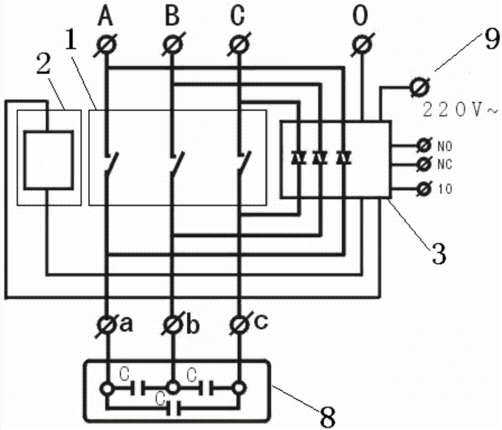
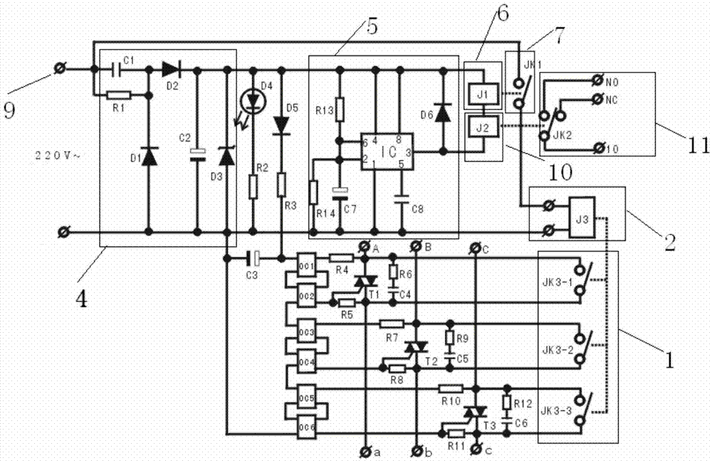
[0018] Such as Figure 1-2 As shown, a compound contactor described in the embodiment of the present invention includes three contactor switches 1 and contactor coil 1 2, and the A-phase power supply terminal, B-phase power supply terminal and C-phase power supply terminal respectively pass through the contactor Switch one 1 is connected with a terminal, b terminal and c terminal, and a line of control signal 9 power supply terminal is connected with the ground terminal through contactor coil one 2, and each contactor switch one 1 is connected in parallel with bidirectional thyristor 3, and the The other line of the power supply end of the control signal 9 is connected to a step-down circuit 4, and a line at the output end of the step-down circuit 4 is connected to C3 and optocouplers OC1-OC6 respectively through D5 and R3, and the optocoupler OC2, optocoupler OC4 and optocoupler OC6 is respectively connected with the control terminals of the bidirectional thyristor 3; another...


PUM


Abstract

The invention relates to a composite contactor which comprises three contactor switches and a contactor coil. A phase-A power end, a phase-B power end and a phase-C power end are connected with an end a, an end b and an end c through the contactor switches, one control signal power end is connected with the ground end through the contactor coil, each contactor switch is connected with TRIAC in parallel, the other control signal power end is connected with a voltage reducing circuit, one output end of the voltage reducing circuit is connected with an optocoupler OC1, an optocoupler OC2, an optocoupler OC3, an optocoupler OC4, an optocoupler OC5 and an optocoupler OC6 through a D5, an R3 and a C3, and the optocoupler OC4 and the optocoupler OC6 are connected with control pole ends of the TRIAC. The other output end of the voltage reducing circuit is connected with a timing circuit which is connected with the contactor coil, and the contactor switches are connected between the control signal power ends and the contactor coil. The composite contactor has the advantages that an existing contactor switch is utilized, and cost is lowered; the TRIAC is used for achieving no-spark on and off, and contact service life is greatly prolonged; the installation and using size of the contactor is completely compatible with the pin-out of an existing contactor, and using is simple and convenient.

Description

technical field [0001] The invention relates to electrical components used in power capacitor switching circuits, in particular to a composite contactor. Background technique [0002] At present, in the power transmission of power lines, in order to improve the power factor of the line, the method of connecting different numbers of power capacitors in parallel is used for compensation. Most of the contactors commonly used for switching capacitors still use the old-fashioned common contact type. The contactor is completed by adding a small resistance wire in the form of current reduction. Although it can reduce the surge current, the pulse spark of the surge current still exists, and the contacts are easily damaged by long-term frequent switching. There are also some capacitive switching circuits that use a composite switch as a solution for switching elements, but due to the installation size of the composite switch, the inconvenient use habits, and the fact that the design ...

Claims


Application Information

Patent Timeline
IPC IPC(8): H02J3/18
CPCY02E40/30
Inventor 郑成锋
Owner 郑成锋
Why Eureka
Try Eureka