
Electrical switching device at junction point between two parts of network

A technology for electrical switches and equipment, which is applied in the installation of electrical switches, grounding switches, and switchgear, etc., and can solve problems such as obstructions.

Inactive Publication Date: 2014-07-02
ALSTOM TECH LTD
View PDF9 Cites 3 Cited by
  • Summary
  • Abstract
  • Description
  • Claims
  • Application Information

AI Technical Summary

Problems solved by technology

Even if there is only one connecting rod, the device still needs to have a considerable length, which prevents it from being installed in some existing networks (wherein the conductors are permanently connected between the shared part and the divided part of the network). Use as a replacement for simple switches

Method used


Image

  • Electrical switching device at junction point between two parts of network
  • Electrical switching device at junction point between two parts of network
  • Electrical switching device at junction point between two parts of network

Examples


Embodiment Construction

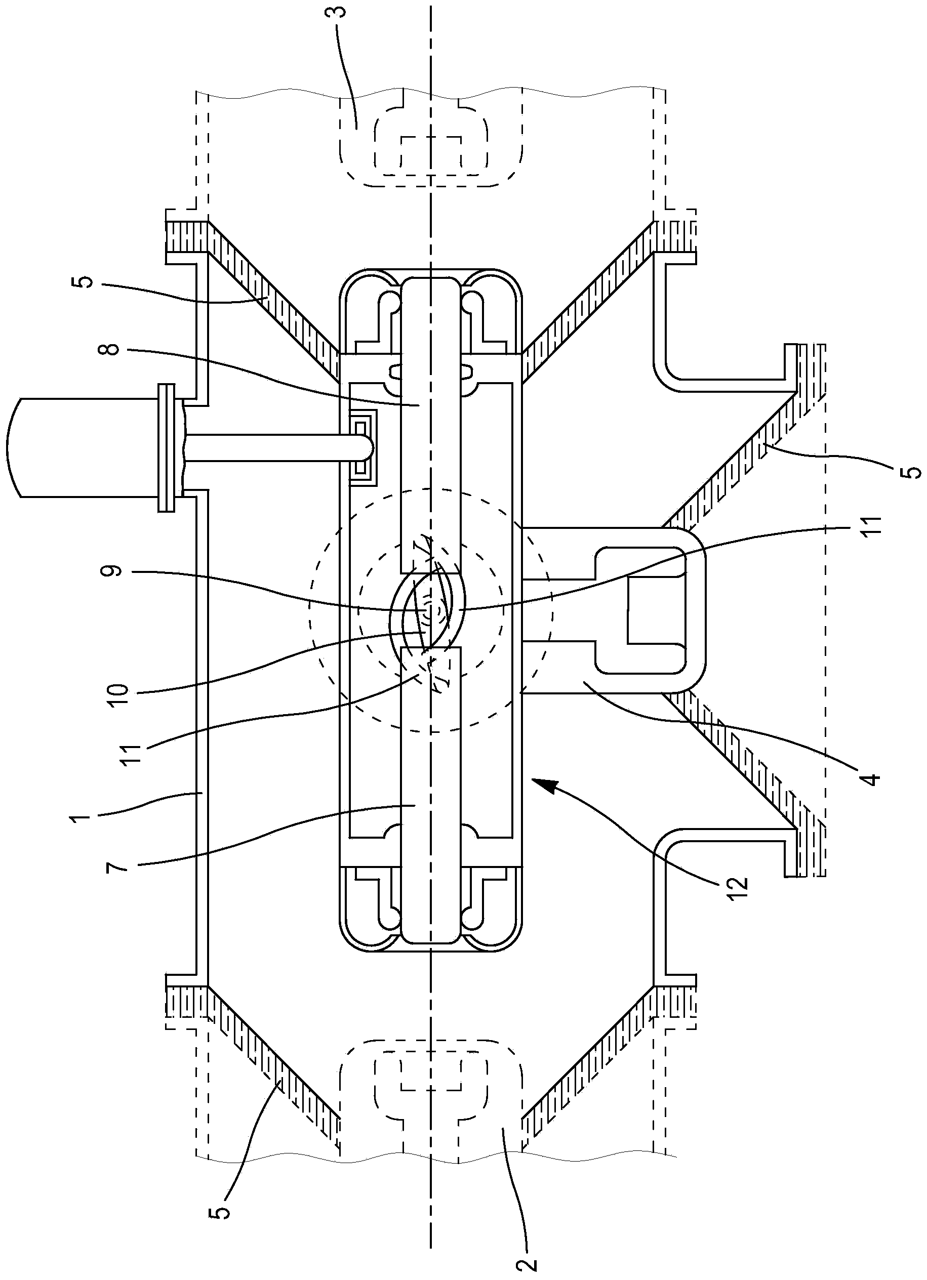
[0025] Reference is made briefly to the device described in US patent document US-A-3553397. In a T-shaped housing (1), a switch with a connecting bar comprises: a joint for connecting the stationary contacts (2 and 3) connected to the ends of the conductors forming the divided part of the network, and for connecting to the shared power conductors The static contact part (4). An electrically insulating barrel, given the general reference number (5), has the stationary contacts (2, 3 and 4) passing therethrough, providing insulation from gases coming from adjacent network compartments. Two linear movable contacts (7 and 8) are aligned in the direction connecting said stationary contacts (2 and 3) and they pass through shafts (9) carrying cranks (10) (only A shaft is visible) for movement, the movable elements (7 and 8) are connected to the crank via a connecting rod (11). The housing (1) comprises a further support (12) in which the movable contacts (7 and 8) slide and are el...


PUM


Abstract

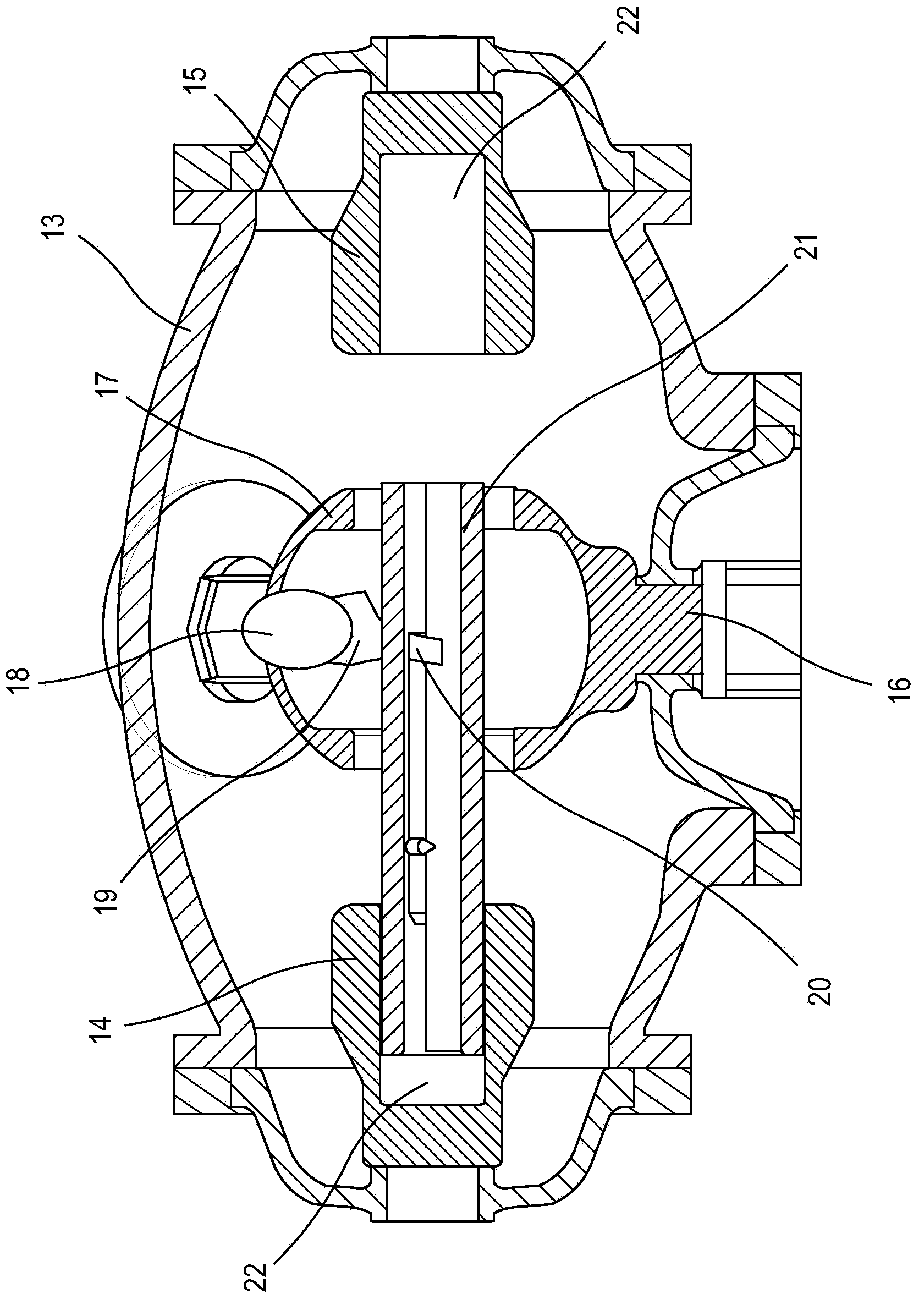
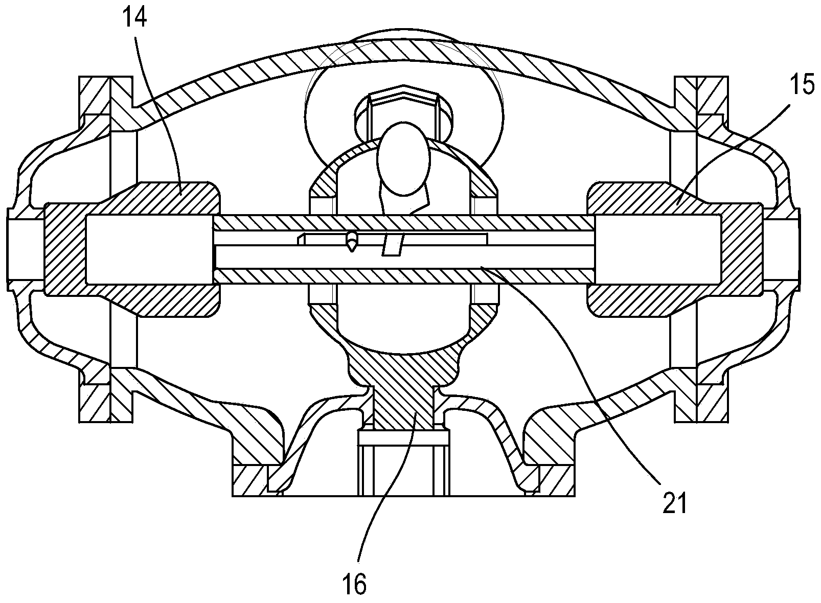
At the junction between a stationary contact (16) belonging to a common part of the network and two stationary contacts (14, 15) belonging to dividing parts of the network, such as busbars, an electrical switch comprises a single moving contact (21), the length of which allows same to enter a recess (22) in one or both of the fixed contacts, depending on the position thereof. The assembly is simplified and reduced in size.

Description

technical field [0001] The invention provides a switching device which is arranged at a junction between two parts into which a network is divided and which provides the possibility of disconnecting one or the other of the two parts. Background technique [0002] High voltage substations make it possible to distribute energy on a network and to protect said network. In the event of a failure or for maintenance, it is advantageous to disconnect an individual part of the network while leaving the other parts running normally. Circuit breakers are provided to provide a disconnection function, however, during maintenance which requires the network to be partially dismantled, it is sometimes necessary to supplement the circuit breakers by means of equipment taking additional insulation distances, especially for applications where the insulating gas is under pressure ( For example, sulfur hexafluoride SF 6 ) in facilities operating in ), because then greater vigilance is require...

Claims


Application Information

Patent Timeline
IPC IPC(8): H01H31/00H01H31/24H02B13/035
CPCH02B13/035H01H31/003H01H31/24
Inventor 伯纳德·热洛兹布鲁诺·加兰德弗里德里克·洛赖阿诺·菲舍
Owner ALSTOM TECH LTD
Learn More