
Transverse shear-resistant reinforcing steel bar connecting device for concrete bridge deck slabs

A technology for lateral connection and shearing steel bars, applied in the direction of bridges, bridge parts, bridge construction, etc., can solve the problem of insufficient space for the arrangement of steel bars, and achieve the effect of convenient installation and accurate stress state of hinges

Inactive Publication Date: 2014-07-09
SOUTHEAST UNIV +1
View PDF5 Cites 2 Cited by
  • Summary
  • Abstract
  • Description
  • Claims
  • Application Information

AI Technical Summary

Problems solved by technology

[0003] Technical problem to be solved: Aiming at the deficiencies of the prior art, the present invention proposes a transverse shear reinforcement connection device for concrete bridge decks, which solves the problem in the prior art that once the deck of the main girder deck is arranged with transverse prestress, it will cause the main girder The technical problem of insufficient space for reinforcement arrangement when horizontally connected cast-in-place sections are connected by traditional methods for transverse shear reinforcement

Method used


Image

  • Transverse shear-resistant reinforcing steel bar connecting device for concrete bridge deck slabs
  • Transverse shear-resistant reinforcing steel bar connecting device for concrete bridge deck slabs
  • Transverse shear-resistant reinforcing steel bar connecting device for concrete bridge deck slabs

Examples


Embodiment Construction

[0030] The present invention will be further described below in conjunction with the accompanying drawings.

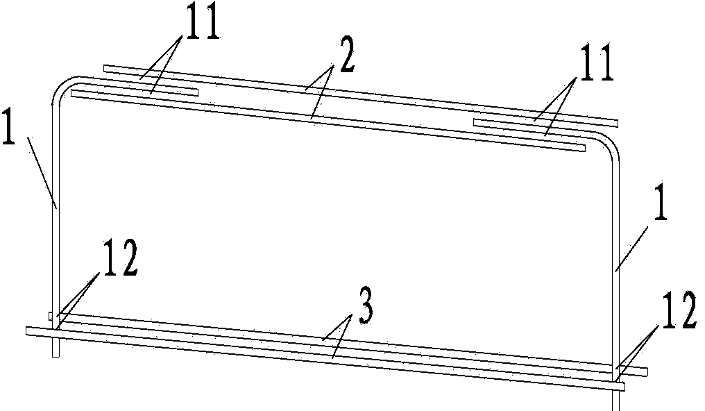
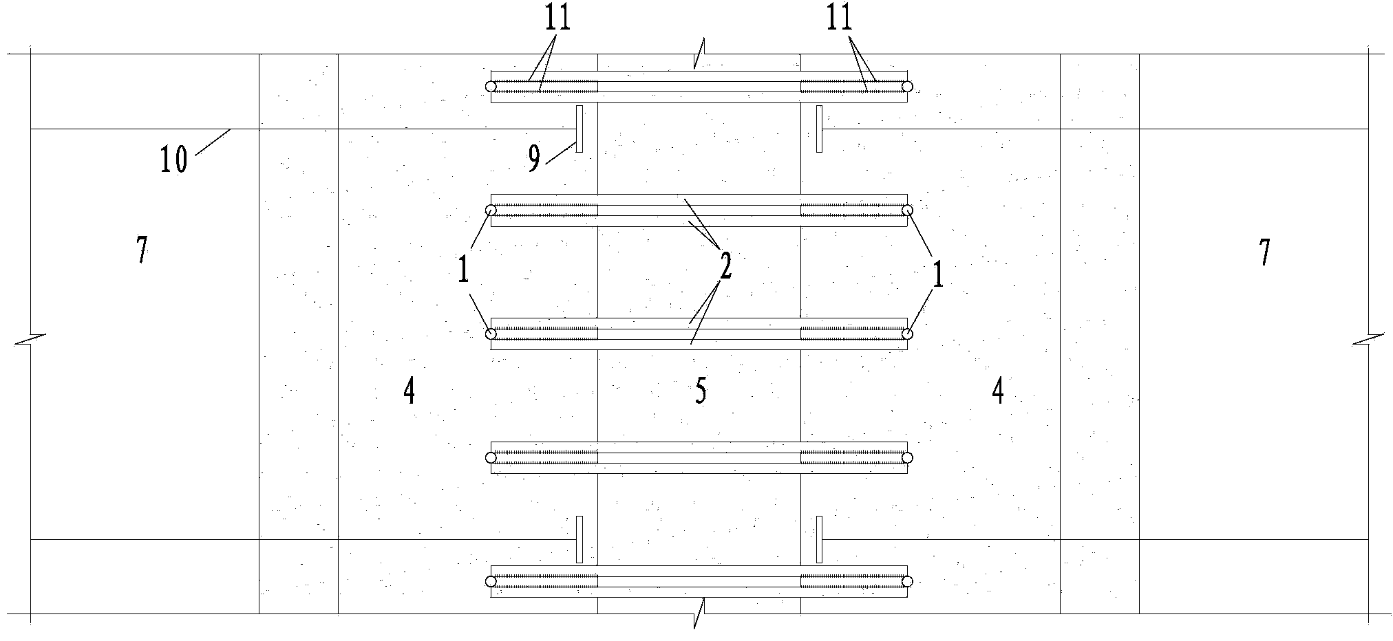
[0031] Such as Figure 1 to Figure 5 As shown, a concrete bridge deck transverse shear reinforcement connection device includes sets of steel bars distributed at intervals of 15 cm along the longitudinal direction of the bridge. Steel bars 3 form a rectangular frame structure;

[0032]The diameter of the vertical steel bar 1 is 18cm, including a vertical main bar and a transverse bend, the transverse bend is arranged on the upper end of the vertical main bar, and the two vertical bars 1 are symmetrical to the two transverse bars to be connected The axis of symmetry of the concrete bridge deck 8 and the vertical main bars are respectively inserted up and down in the two concrete bridge decks 8. The concrete bridge deck 8 can be either a cast-in-place bridge deck or a prefabricated bridge deck. Just expose the top surfaces of the two concrete bridge decks 8 to be conne...


PUM

PropertyMeasurementUnit
Diameteraaaaaaaaaa
Diameteraaaaaaaaaa

Abstract

The invention discloses a transverse shear-resistant reinforcing steel bar connecting device for concrete bridge deck slabs. The transversely connected bridge deck slabs which are of rectangular frame structures comprise vertical reinforcing steel bars, top transverse connecting reinforcing steel bars and bottom transverse connecting reinforcing steel bars, and hinged stress states of bridge deck slabs can be simulated by the aid of elastic extension and retraction effects of the transverse reinforcing steel bars. The vertical reinforcing steel bars are arranged at the rears of flat anchors and penetrate the bottoms of the bridge deck slabs from the tops of the bridge deck slabs, so that spaces occupied by the flat anchors can be avoided, and the transverse connecting shear-resistant reinforcing steel bars can be arranged between the bridge deck slabs at certain intervals without spatial constraints. The transverse shear-resistant reinforcing steel bar connecting device has the advantages that the transverse shear-resistant reinforcing steel bars of the bridge deck slabs can be arranged without the spatial constraints, so that designed requirements on transverse connection between the bridge deck slabs can be assuredly met; the hinged stress states of the bridge deck slabs are accurate owing to the rectangular frame structures comprising the vertical reinforcing steel bars, the top transverse connecting reinforcing steel bars and the bottom transverse connecting reinforcing steel bars.

Description

technical field [0001] The invention relates to a bridge construction project, and is particularly suitable for a bridge deck transverse shearing reinforcement connection device for transversely connecting cast-in-place sections of main girders. Background technique [0002] When setting the transverse prestress on the deck of the main girder, there must be a space for the arrangement of corresponding flat anchors (hereinafter referred to as "flat anchors") at the transverse end of the deck. Generally speaking, the width of the flat anchor is about 20cm, and the flat anchor along the bridge The vertical spacing is 50cm. Obviously, there is no room for the traditional horizontal shear reinforcement layout according to the traditional method, that is, inserting two bridge decks horizontally to connect them horizontally and form a hinge bearing state. If the horizontal reinforcement arrangement is simply avoided in the anchorage space of the flat anchor, the spacing of the hori...

Claims


Application Information

Patent Timeline
IPC IPC(8): E01D19/12
Inventor 熊文张娟秀叶欣姚伟发叶见曙
Owner SOUTHEAST UNIV
Learn More