A method for controlling straightness of hydraulic support group in working face using optical fiber

A technology of hydraulic support and control method, which is applied in the direction of pillars/supports, earth cube drilling, mining equipment, etc., which can solve the problems of inaccurate straightening, unfavorable popularization and application, and great influence of information transmission, etc., and achieves convenient transformation and low cost Effect

Active Publication Date: 2016-05-18
BEIJING TIANMA INTELLIGENT CONTROL TECH CO LTD
View PDF4 Cites 0 Cited by
  • Summary
  • Abstract
  • Description
  • Claims
  • Application Information

AI Technical Summary

Problems solved by technology

[0003] At present, the working surface of the hydraulic support manual system is all manually pushed or pulled by the hydraulic support on the working surface to control the straightening of the scraper conveyor. A few systems that use sensors for straightness correction have a complex structure and a large number of sensors. The information transmission is greatly affected by the underground environment, and the alignment is not accurate enough. At the same time, the installation needs to make major changes to the existing working face support system, which is not conducive to large-scale promotion and application.

Method used


Image

  • A method for controlling straightness of hydraulic support group in working face using optical fiber
  • A method for controlling straightness of hydraulic support group in working face using optical fiber

Examples


Embodiment Construction

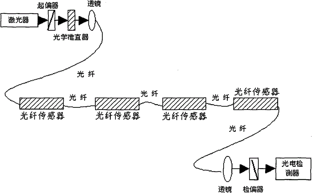
[0008] see figure 1 , which describes a preferred embodiment of the straightness control method of the working face hydraulic support group using optical fiber according to the present invention. The execution system of the straightness control method of the working face hydraulic support group using optical fiber includes a laser, a polarizer, 4 optical fiber sensors, a polarizer and a photoelectric detector; a laser, a polarizer, multiple fiber optic sensors, a polarizer and The photodetectors are connected in sequence. In order to ensure the quality of light transmission, an optical collimator and a lens can be arranged between the polarizer and the fiber sensor. Similarly, a lens can also be arranged between the analyzer and the fiber sensor.

[0009] The polarizer and optical fiber sensor, multiple optical fiber sensors, optical fiber sensor and polarizer are connected by optical fiber; the optical fiber sensor includes a steel plate and an optical fiber section fixed on ...


PUM


Abstract

Disclosed is a method using optical fibers for controlling the straightness of a working surface hydraulic support group. Optical fiber strain sensors are arranged between two adjacent chutes of the working surface hydraulic support group. A laser device, a polarizer, a plurality of optical fiber sensors, an analyzer and a photoelectric detector are connected sequentially, and the polarizer, the optical fiber sensors and the analyzer are connected through an optical fiber to form a optical fiber circuit; the laser device emits laser signals, and the photoelectric detector detects Brillouin frequencies of laser signals in real time; after the working surface hydraulic support group is pushed and moved, whether the positions of the hydraulic supports are not in places or are pushed over can be judged according to the offset of the Brillouin frequencies of the laser signals, and the hydraulic supports which are not in places or which are pushed over are adjusted by controlling a working surface electro-hydraulic control system. According to the method, detection of working surface hydraulic supports which are not in places or which are pushed over can be implemented through the optical fiber and the optical fiber sensors, the working surface electro-hydraulic control system is combined, the straightness of the working surface hydraulic support group can be controlled automatically in an unattended manner, only one controller and one optical fiber provided with sensors are arranged as required by the entire system, optimization is facilitated, cost is low, and the method is adaptive to large-scale promotion in coal mines.

Description

technical field [0001] The invention relates to a straightness control system of a hydraulic support group of a working face, in particular to a straightness control system of a hydraulic support group of a working face using an optical fiber. Background technique [0002] The fully mechanized mining face is composed of shearer, scraper conveyor, hydraulic support and other equipment. The scraper conveyor is composed of a section of a chute connected. The connecting hole of the scraper conveyor and the hydraulic support push rod connection head are fixed and connected by pins, and the telescopic action of the jack is pushed through the hydraulic support on the working surface. Realistic scraper conveyor of the mobile. Multiple hydraulic supports are arranged in sequence on the working surface, and their respective positions are constrained by the scraper conveyor on the working surface, but their mutual positions are not constrained, which is a semi-floating system. During...

Claims


Application Information

Patent Timeline
Patent Type & Authority Patents(China)
IPC IPC(8): E21D15/51
Inventor 张守祥冯银辉李重重李沛轩
Owner BEIJING TIANMA INTELLIGENT CONTROL TECH CO LTD
Why Eureka
Try Eureka