LED uniform-collimation optical system

An optical system and uniform technology, applied in the field of collimating optical systems, can solve the problems of insufficient light efficiency of the lens, inability to collect all the light of the LED, affecting the propagation distance of the system, etc., and achieve the effect of good light control ability.

Inactive Publication Date: 2014-07-09
NAVAL UNIV OF ENG PLA
View PDF5 Cites 7 Cited by
  • Summary
  • Abstract
  • Description
  • Claims
  • Application Information

AI Technical Summary

Problems solved by technology

However, due to the phenomenon of total reflection between different refractive index media, this kind of lens cannot collect all the light of the LED, so the light efficiency of the lens is not high enough, which affects the propagation distance of the entire system

Method used


Image

  • LED uniform-collimation optical system
  • LED uniform-collimation optical system
  • LED uniform-collimation optical system

Examples


Embodiment Construction

[0023] Below in conjunction with accompanying drawing and specific embodiment the present invention is described in further detail:

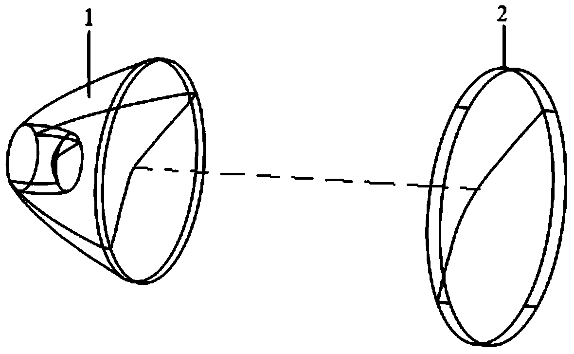
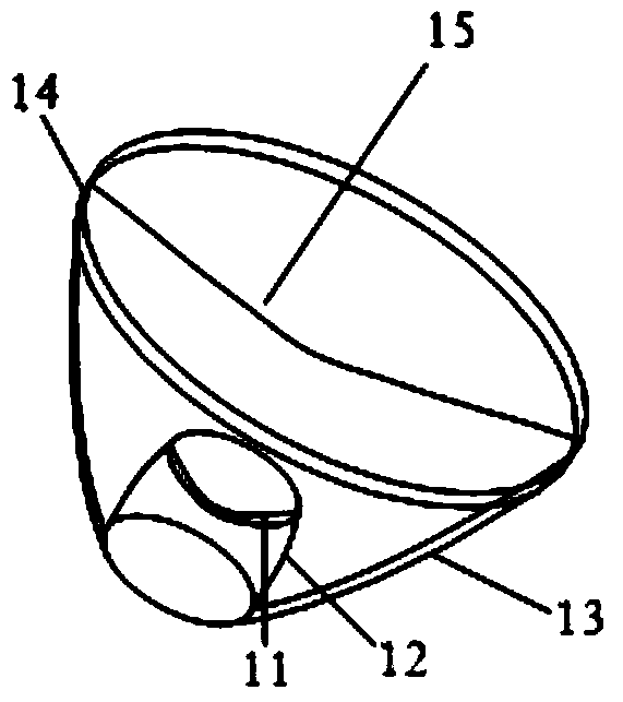
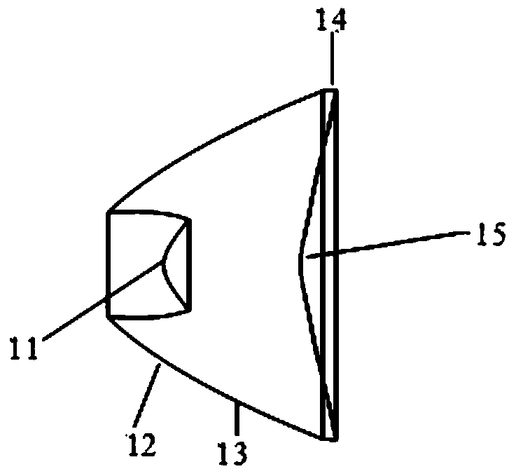
[0024] Figure 1-4 The optical system for LED uniform collimation shown in , includes a first free-form surface lens 1 and a second free-form surface lens 2 coaxially arranged, and the distance between the first free-form surface lens 1 and the second free-form surface lens 2 is 0.01m-0.1 m; the first free-form surface lens 1 includes a first curved surface 11, which is a rotationally symmetrical free-form surface for refracting the light emitted by the LED so that the refracted light is parallel to the z-axis, and the LED light controlled by the free-form surface is aligned with the z-axis The included angle is determined by the refractive index of the lens material; the second curved surface 12 is a rotationally symmetrical free-form surface, which is used to refract the light emitted by the LED so that the refracted light coincides with the l...


PUM


Abstract

The invention relates to the technical field of LED lighting collimation optical system, in particular to an LED uniform-collimation optical system comprising a first free-form surface lens and a second free-form surface lens which are coaxial. The first and second free-form surface lenses are 0.01m-0.1m in spacing. The first free-form surface lens comprises a first surface which is a rotational symmetric free-form surface, a second surface which is a rotational symmetric free-form surface, a third surface which is a rotational symmetric paraboloid, a fifth surface which is a rotational symmetric free-form surface, and a fourth surface which is a cylindrical surface used for connecting the third surface and the fifth surface. The second free-form surface lens comprises three surfaces; the first surface is a free-form surface and controls the direction of light from the second free-from surface lens; the second surface and the third surface are a connecting surface and a light emission face of the second free-form surface lens respectively. The system is well capable of controlling the light and capable of shaping the LED light into uniform round light spots.

Description

technical field [0001] The invention relates to the technical field of collimating optical systems for LED lighting, in particular to an optical system for uniformly collimating LEDs. technical background [0002] As a new type of light source, LED is a perfect substitute for traditional light sources such as incandescent lamps and fluorescent lamps due to its high luminous efficiency, long life, and non-toxicity. However, since the light intensity distribution of LED is a circular Lambertian distribution, if it is directly applied to lighting, it will form an extremely uneven illuminance distribution on the target surface, which cannot meet the optical performance requirements of various lighting occasions for lamps. In order to make LEDs better used in the lighting field, it is necessary to design a secondary optical system to redistribute the light intensity distribution of LEDs so that it can form a uniform or other specific illuminance distribution on the target surface...

Claims


Application Information

Patent Timeline
Patent Type & Authority Applications(China)
IPC IPC(8): F21V5/04F21Y101/02F21Y115/10
Inventor 张晓晖陈琛陈亮程刚
Owner NAVAL UNIV OF ENG PLA
Why Eureka
Try Eureka