Eureka AIR delivers breakthrough ideas for toughest innovation challenges, trusted by R&D personnel around the world.

Electroluminescent device, manufacturing method and driving method thereof, and display device

a technology of electroluminescent devices and manufacturing methods, applied in the field of display technology, can solve the problems of inability to adjust the color temperature of white light, the type device cannot avoid extra power consumption, and the color variation of color becomes uncontrollable, so as to reduce the loss of optical waveguides in the device, the effect of increasing the light emitting efficiency of the devi

Active Publication Date: 2017-07-06
BOE TECH GRP CO LTD +1
View PDF9 Cites 5 Cited by
  • Summary
  • Abstract
  • Description
  • Claims
  • Application Information

AI Technical Summary

Benefits of technology

The present invention provides an electroluminescent device and a manufacturing method and driving method thereof, as well as a display device, that solves the problems of uncontrollable color temperature and low lighting efficiency in existing electroluminescent devices. The invention uses a parallel device structure to achieve independent control of two light emitting units in a single electroluminescent device, allowing for optimized and tuned individual units. This results in not only adjustable color temperature but also increased lighting efficiency of the device. Additionally, the transparent substrate can be fabricated using polymers that reduce optical waveguide loss and allow for flexible display.

Problems solved by technology

Laminated type devices tend to have exciplex quenching at the layer interface, and as the brightness of the device increases, the color temperature variation becomes uncontrollable.
The series type devices can hardly avoid extra power consumption caused by poor contact of the light emitting layers, and cannot achieve adjustment of white light color temperature.

Method used


Image

  • Electroluminescent device, manufacturing method and driving method thereof, and display device
  • Electroluminescent device, manufacturing method and driving method thereof, and display device

Examples


Embodiment Construction

[0063]Hereinafter embodiment of the present invention will be described with reference to the accompanying drawings. It should be understood that the embodiments described herein are intended to illustrate and explain the present invention, rather than limit the present invention.

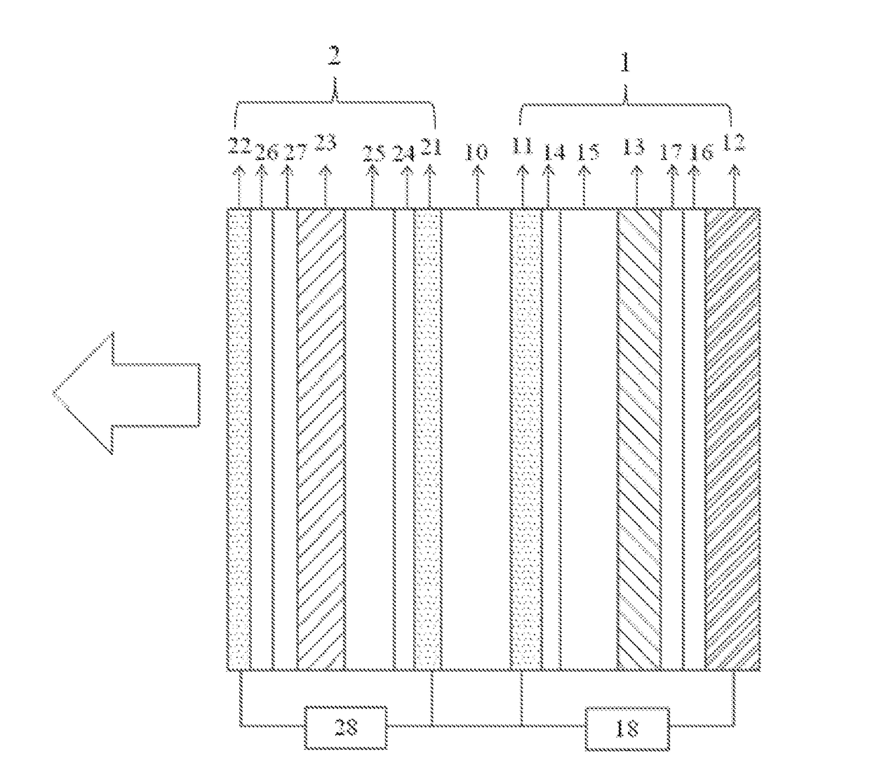
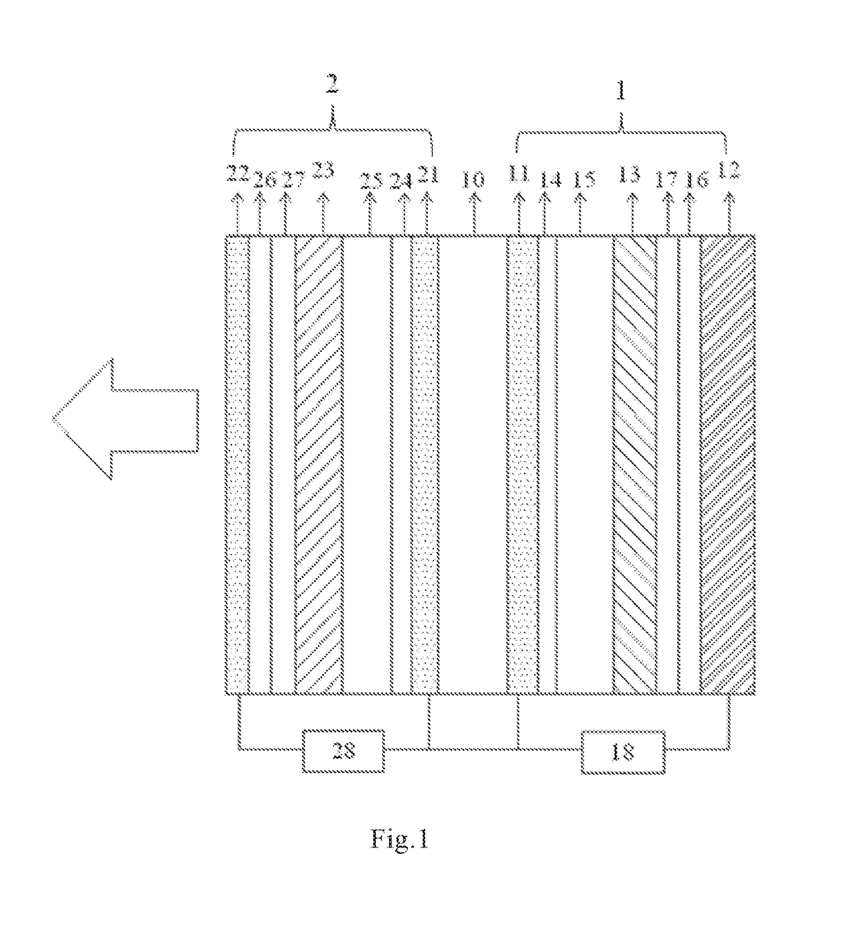
[0064]The present invention provides an electroluminescent device as shown in FIG. 1, which comprises a transparent substrate 10, and a first light emitting unit 1 and a second light emitting unit 2 disposed at both sides of the transparent substrate 10 respectively, and the first light emitting unit 1 and the second light emitting unit 2. have the same light output direction and are connected to two control circuits respectively.

[0065]For example, in FIG. 1, the first light emitting unit 1 and the second light emitting unit 2 are controlled respectively by a first control circuit 18 and a second control circuit 28 independent to each other. The light output direction is the direction along which the light ...


PUM


Abstract

The present invention provides an electroluminescent device, a manufacturing method and driving method thereof, and a display device. The electroluminescent device comprises a transparent substrate, and a first light emitting unit and a second light emitting unit disposed at both sides of the transparent substrate respectively, wherein the first light emitting unit and the second light emitting unit have the same light output direction and are connected to two control circuit respectively. In the present invention, a parallel device structure is adopted to achieve independent control of two light emitting units in a single electroluminescent device, not only the color temperature is adjustable, but also the light emitting efficiency of the device can be increased. Also the transparent substrate can be fabricated using polymers having a refractive index adapted to the light emitting material, thereby reducing the optical waveguide loss in the device and realizing display of flexible device.

Description

FIELD OF THE INVENTION[0001]The present invention relates to the field of display technology, in particular to an electroluminescent device, a manufacturing method and driving method thereof, and a display device.BACKGROUND OF THE INVENTION[0002]An existing electroluminescent device includes laminated type and series type. The above two types of device have the following defects due to limitation in the device structure:[0003]Laminated type devices tend to have exciplex quenching at the layer interface, and as the brightness of the device increases, the color temperature variation becomes uncontrollable. The series type devices can hardly avoid extra power consumption caused by poor contact of the light emitting layers, and cannot achieve adjustment of white light color temperature.[0004]Therefore, it has very important significance and application value in both display and lighting fields to realize controllable color and efficient light output in a same device structure.SUMMARY OF...

Claims


Application Information

Patent Timeline
IPC IPC(8): G09G3/3208H01L51/56H01L51/52H01L51/00H01L27/32H05B44/00
CPCG09G3/3208G09G2320/0233H01L27/3206H01L51/5206H01L51/5221H01L51/56H01L2251/5315H01L51/5088H01L51/5056H01L51/5092H01L2251/308H01L2251/558H01L2251/301H01L2251/5307H01L51/5072H01L51/0078H01L51/0072H01L51/005H01L51/006H01L51/0058H01L51/0056H01L51/0081H01L51/0085G09G2320/0666H01L51/0096H05B45/00H10K59/32H10K50/131H10K50/17H10K59/8052G09G3/14Y02E10/549Y02P70/50H10K59/128H10K50/81H10K50/82H10K59/30H10K71/00H10K77/10H10K50/15H10K50/16H10K50/171H10K85/60H10K85/311H10K85/324H10K85/342H10K85/624H10K85/626H10K85/633H10K85/6572H10K2102/00H10K2102/103H10K2102/351H10K2102/3023H10K2102/3026
Inventor ZHANG, XIAOJINFENG, XIANGXIE, DINI
Owner BOE TECH GRP CO LTD
Why Eureka
Eureka Blog
Learn More