
Light-emitting electronic textile with improved light diffusion

a technology of electronic textiles and light diffusion, applied in the field of light-emitting electronic textiles, can solve the problems of relatively large spacing between adjacent light sources and low resolution of current light-emitting electronic textiles, and achieve the effect of improving light-emitting electronic textiles

Inactive Publication Date: 2014-04-08
KONINK PHILIPS ELECTRONICS NV
View PDF12 Cites 13 Cited by
  • Summary
  • Abstract
  • Description
  • Claims
  • Application Information

AI Technical Summary

Benefits of technology

The present invention aims to improve light-emitting electronic textiles. The technical effects of this invention include overcoming the limitations and shortcomings of existing technologies, providing better performance and efficiency, and addressing common issues associated with textiles.

Problems solved by technology

In general, currently available light-emitting electronic textiles have a rather low resolution, that is, the spacing between adjacent light-sources is relatively large.

Method used


Image

  • Light-emitting electronic textile with improved light diffusion
  • Light-emitting electronic textile with improved light diffusion
  • Light-emitting electronic textile with improved light diffusion

Examples


Embodiment Construction

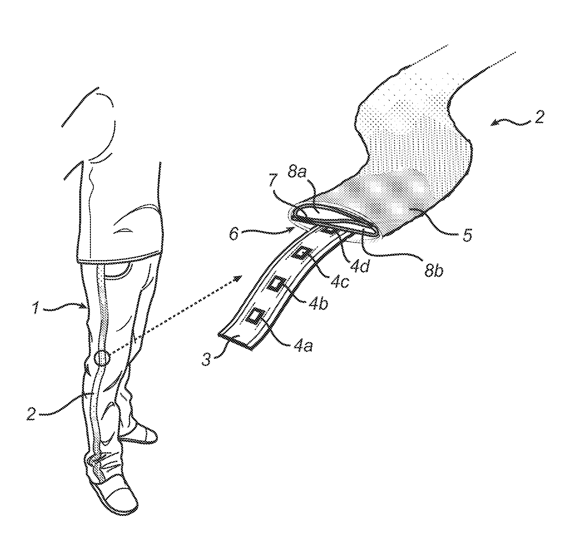
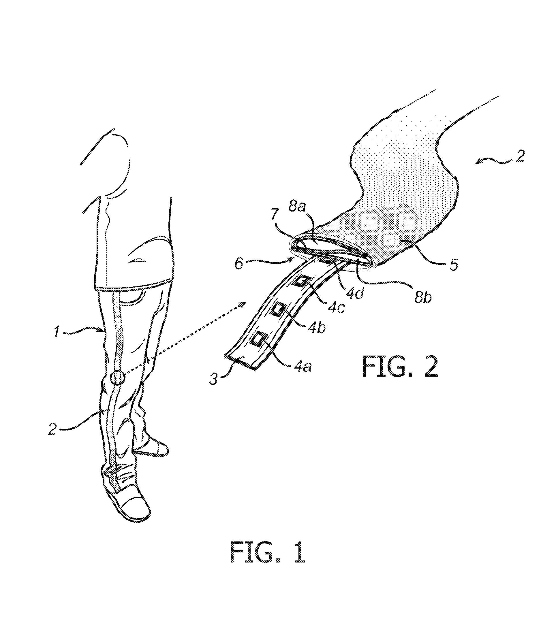
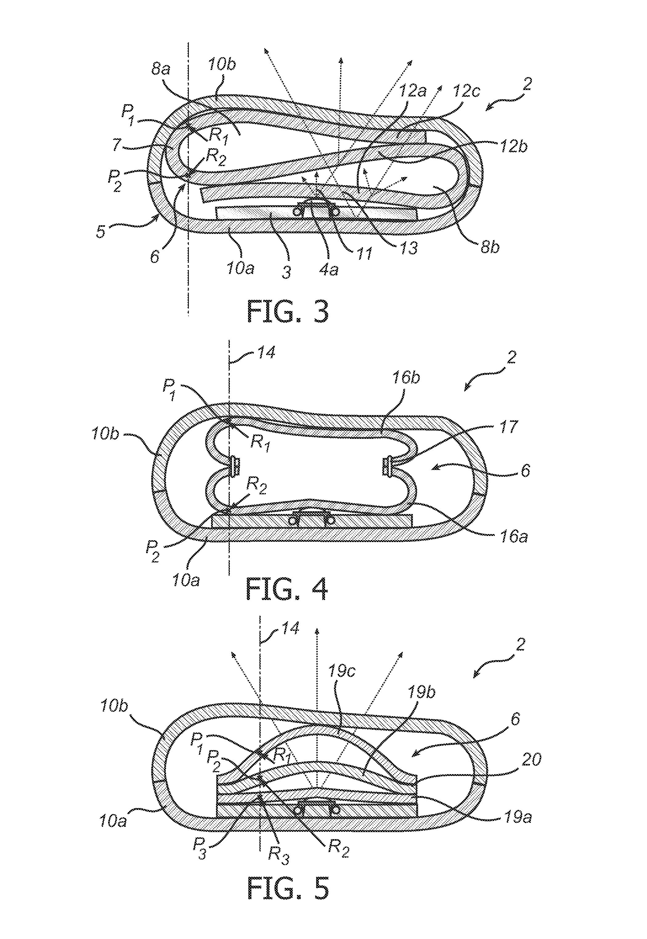
[0038]In the following description, the present invention is described with reference to a light-emitting electronic textile in which the light-diffusing member is formed by one or several sheets of a non-woven textile material enclosed by tubular cover textile.

[0039]It should be noted that this by no means limits the scope of the invention, which is equally applicable to other light-emitting electronic textiles in which the cover textile is differently provided, for example as a one-sided cover being attached to the flexible component carrier. Furthermore, the light-diffusing member can be formed by a layered structure in any other suitable layered configuration formed by a plurality of light-diffusing layers, such as woven textile layers, foam layers or layers of different light-diffusing materials suitable for use in a light-emitting electronic textile.

[0040]FIG. 1 schematically illustrates an exemplary application for various embodiments of the light-emitting electronic textile ...


PUM

PropertyMeasurementUnit
flexibleaaaaaaaaaa
radii of curvatureaaaaaaaaaa
thicknessaaaaaaaaaa

Abstract

A light-emitting electronic textile (2) comprising a flexible component carrier (3) having a plurality of light-sources (4a-c) arranged thereon; a cover textile (5) arranged to allow passage through the cover textile (5) of light emitted by the light-sources (4a-c); and a light-diffusing member (6) arranged between the light-sources (4a-c) and the cover textile (5). The light-diffusing member (6) comprises a layered structure formed by a plurality of light-diffusing layers (12a-c; 16a-b; 19a-c), wherein adjacent light-diffusing layers in the layered structure are spaced apart at least in portions of the light-diffusing member (6) corresponding to positions of the light-sources (4a-c).

Description

FIELD OF THE INVENTION[0001]The present invention relates to a light-emitting electronic textile and to a method for manufacturing such a light-emitting electronic textile.BACKGROUND OF THE INVENTION[0002]By integrating light-sources, such as light-emitting diodes (LEDs), into textile applications and thereby creating light-emitting electronic textiles, attractive visual effects can be achieved.[0003]In general, currently available light-emitting electronic textiles have a rather low resolution, that is, the spacing between adjacent light-sources is relatively large. Furthermore, it has been found that end users often prefer that the light-emitting electronic textile gives the impression that the light-sources are not isolated spots of light.[0004]For this reason, currently proposed light-emitting electronic textiles may be provided with a diffusing element arranged on top of the light-sources to achieve a more uniform output of light from the light-emitting electronic textile.[0005...

Claims


Application Information

Patent Timeline
Patent Type & Authority Patents(United States)
IPC IPC(8): F21V1/00F21V11/00
CPCG09F13/22G09F23/04A41D27/085G09F21/02F21Y2101/02F21V33/0008F21Y2115/10Y10T29/49002
Inventor UBAGHS, GUY WILHELMUS MARIEBHATTACHARYA, RABIN
Owner KONINK PHILIPS ELECTRONICS NV
Learn More