Light source having light blocking components

a technology of light blocking components and light sources, which is applied in the direction of semiconductor devices, basic electric elements, electrical equipment, etc., can solve the problems of non-monochromatic light, and achieve the effect of enhancing the light emission from the top surface of the electroluminescent devi

Inactive Publication Date: 2011-06-30
3M INNOVATIVE PROPERTIES CO
View PDF46 Cites 14 Cited by
  • Summary
  • Abstract
  • Description
  • Claims
  • Application Information

AI Technical Summary

Benefits of technology

[0007]In another embodiment, a light emitting system includes a light reflector that reflects light at a first wavelength λ1. The light emitting system further includes an electroluminescent device that is disposed on the light reflector and emits light at the first wavelength. The electroluminescent device has an active region for generating photons at the first wavelength. The distance between the active region and the light reflector is such that emission of light from the top surface of the electroluminescent device is enhanced and emission of light from one or more sides of the electroluminescent device is suppressed. The light emitting system further includes a re-emitting semiconductor construction that includes a II-VI potential well and receives the first wavelength light that exits the electroluminescent device from the top surface and converts at least a portion of the received light to light of a second wavelength. The integrated emission intensity of all light at the second wavelength that exit the light emitting system is at least 4 times the integrated emission intensity of all light at the first wavelength that exit the light emitting system. In some cases, the light reflector includes a metal. In some cases, the light reflector includes a Bragg reflector. In some cases, the light reflector is capable of laterally spreading an electric current across the LED. In some cases, the distance between the active region and the light reflector is in a range from about 0.6λ1 to about 1.4λ1. In some cases, this distance is in a range from about 0.6λ1 to about 0.8λ1. In some cases, this distance is in a range from about 1.2λ1 to about 1.4λ1. In some cases, light that is emitted by the light emitting system along a first direction has a first set of color coordinates and light that is emitted by the light emitting system along a second direction has a second set of color coordinates that are substantially the same as the first set of color coordinates. In such cases, the angle between the first and second directions is no less than 20 degrees. In some cases, the first set of color coordinates are u1′ and v1′ and the second set of color coordinates are u2′ and v2′, and the absolute value of each of differences between u1′ and u2′ and between v1′ and v2′ is no more than 0.01.

Problems solved by technology

In such known devices, however, some of the unconverted blue light leaks and mixes with the red light resulting in non-monochromatic light.

Method used


Image

  • Light source having light blocking components
  • Light source having light blocking components
  • Light source having light blocking components

Examples


example 1

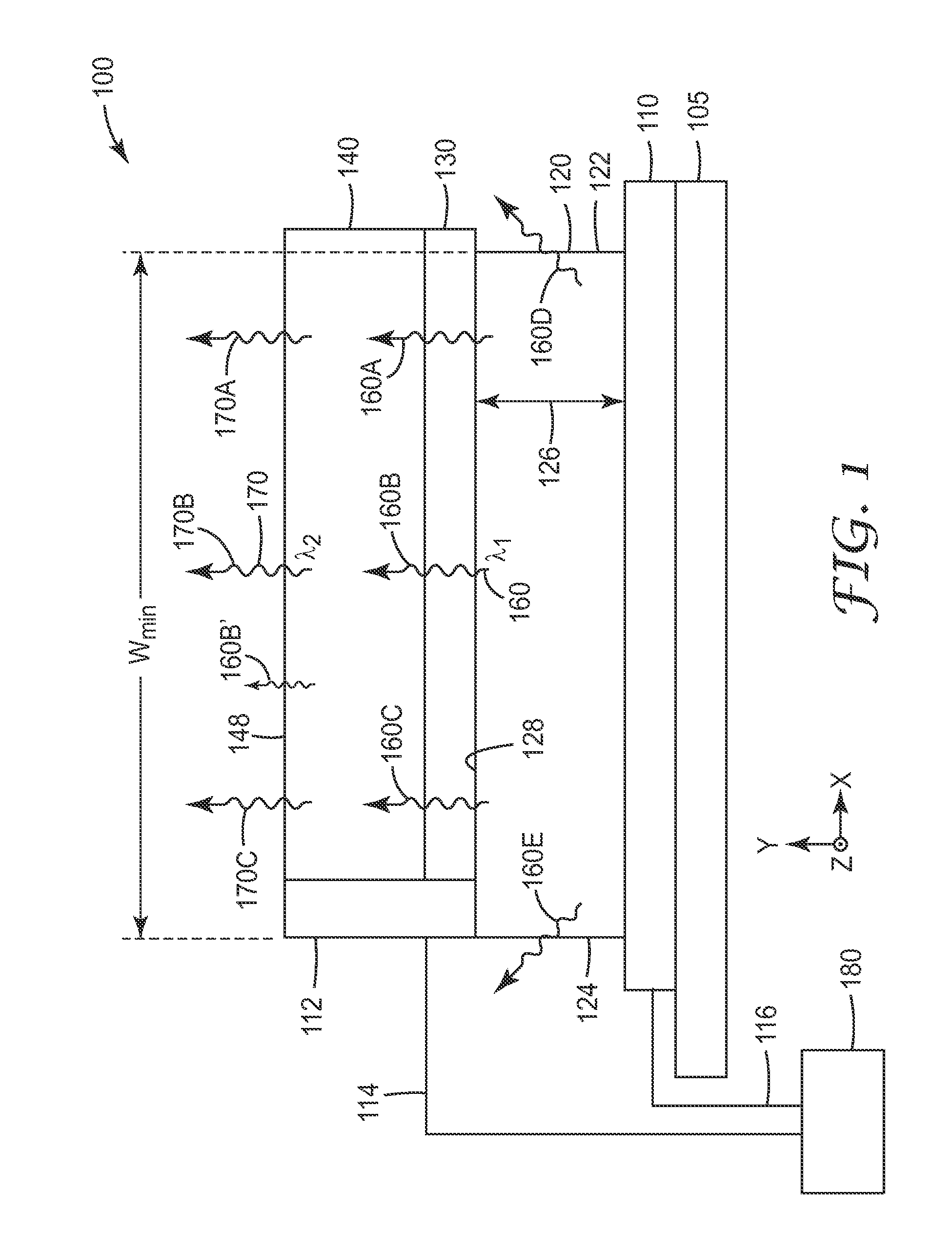
[0102]An amber emitting light emitting system similar to light emitting system 100 was fabricated. An LED capable of emitting light at λ1=455 nm was purchased from Epistar Corporation (Hsin Chu, Taiwan). The LED was an epitaxial AlGaInN-based LED bonded to a silicon wafer. Some portions of the top surface of the LED wafer were metalized with gold traces to spread the current and to provide pads for wire bonding.

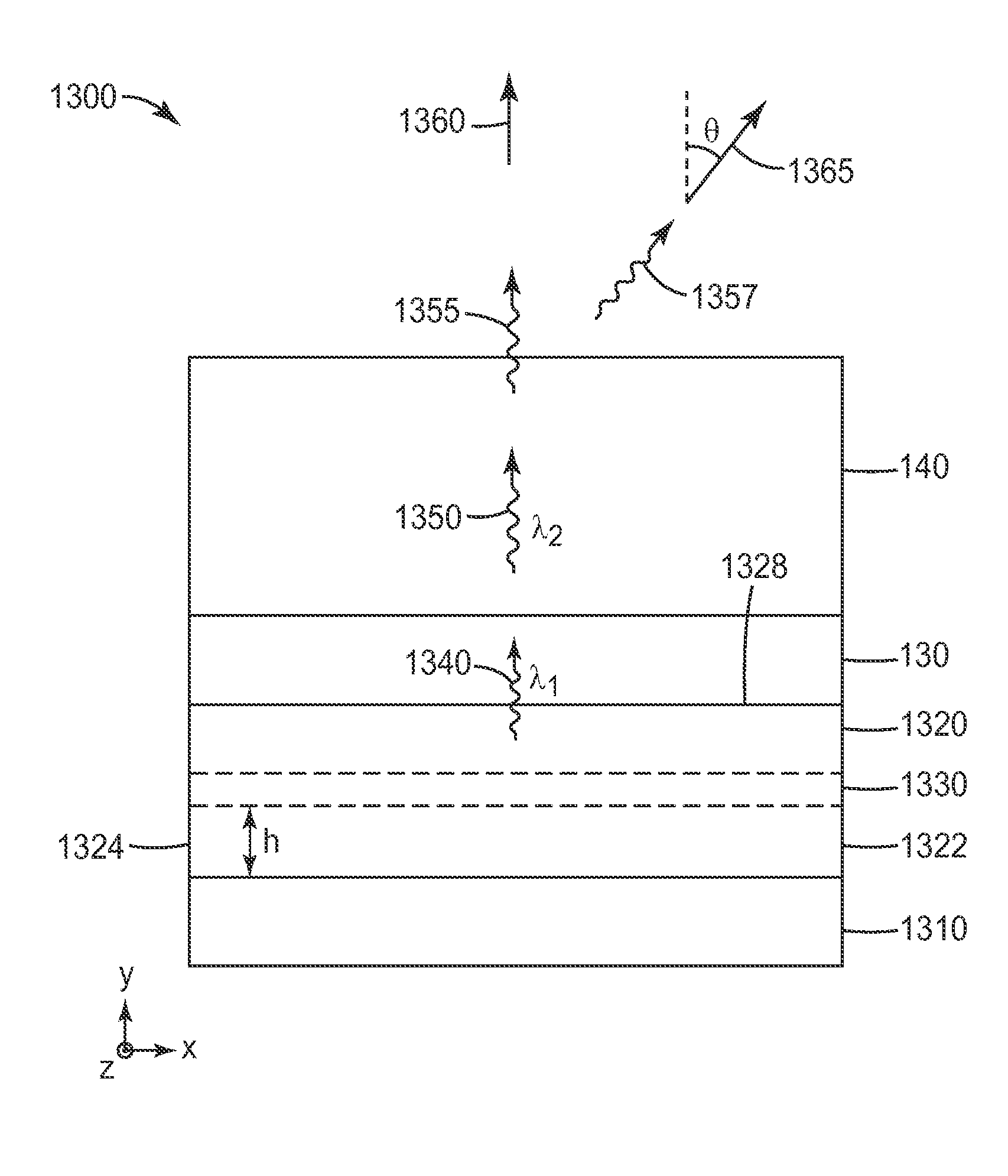
[0103]A multilayer re-emitting semiconductor construction similar to re-emitting construction 140 was fabricated. The relative layer sequence and estimated values of material composition, thickness and bulk band gap energy are summarized in Table I.

[0104]A GaInAs buffer layer was first grown on an InP substrate by molecular beam epitaxy (MBE) to prepare the surface for subsequent II-VI growth. The coated substrate was then moved through an ultra-high vacuum transfer system to another MBE chamber for growth of different II-VI epitaxial layers. The re-emitting semiconductor con...


PUM


Abstract

Light emitting systems are disclosed. The light emitting system includes an electroluminescent device that emits light at a first wavelength from a top surface of the electroluminescent device. The light emitting system further includes a construction proximate a side of the electroluminescent device for blocking light at the first wavelength that would otherwise exit the side. The light emitting system further includes a re-emitting semiconductor construction that includes a II-VI potential well. The re-emitting semiconductor construction receives the first wavelength light that exits the electroluminescent device and converts at least a portion of the received light to light of a second wavelength. The integrated emission intensity of all light at the second wavelength that exit the light emitting system is at least 4 times the integrated emission intensity of all light at the first wavelength that exit the light emitting system.

Description

FIELD OF THE INVENTION[0001]This invention generally relates to semiconductor light emitting devices. The invention is particularly applicable to monochromatic semiconductor light emitting devices.BACKGROUND[0002]Monochromatic light emitting diodes (LEDs) are becoming increasingly important for optical, such as illumination, applications. One example of such an application is in the back-illumination of displays, such as liquid crystal display (LCD) computer monitors and televisions. Wavelength converted light emitting diodes are increasingly used in applications where there is a need for light of a color that is not normally generated, or is not generated efficiently, by an LED. Some known light emitting devices include a light source, such as an LED, that emits, for example, blue light and a light converting layer for converting the blue light to, for example, red light. In such known devices, however, some of the unconverted blue light leaks and mixes with the red light resulting...

Claims


Application Information

Patent Timeline
Patent Type & Authority Applications(United States)
IPC IPC(8): H01L33/06
CPCH01L33/04H01L33/50H01L33/44H01L33/08
Inventor LEATHERDALE, CATHERINE A.HAASE, MICHAEL A.BALLEN, TODD A.MILLER, THOMAS J.
Owner 3M INNOVATIVE PROPERTIES CO
Why Eureka
Try Eureka