Illumination apparatus and automobile equipped with same

a technology of illumination apparatus and automobile body, which is applied in the direction of lighting and heating apparatus, instruments, transportation and packaging, etc., can solve the problems of low light efficiency of the apparatus, difficulty in freely changing the outer shape of the illumination apparatus, and lower freedom of disposition, so as to facilitate the restriction of the position of the vehicle body where the illumination apparatus is placed, and achieve high light efficiency. , the effect of high visibility

Active Publication Date: 2018-05-29
PANASONIC INTELLECTUAL PROPERTY MANAGEMENT CO LTD
View PDF9 Cites 5 Cited by
  • Summary
  • Abstract
  • Description
  • Claims
  • Application Information

AI Technical Summary

Benefits of technology

[0009]Meanwhile, with regard to the conventional daytime-running illumination apparatus using a light guide plate, it is easy to form a line-shaped light source with excellent visibility and design properties, and the freedom of the disposition is also high. However, such an illumination apparatus has a problem of low light efficiency. Specifically, in the daytime-running illumination apparatus using a light guide plate, loss of light occurs when the light enters from the LEDs into the light guide plate, and large loss of light occurs when the light is extracted from the light guide plate. Consequently, the light efficiency is generally low.
[0010]In view of the above problems, as well as other concerns, an object is to provide an illumination apparatus that has high light efficiency, high freedom of disposition thereof, and excellent visibility, as well as an automobile including the illumination apparatus.
[0014]Thus, since the emitted light will be recognized as a continuous line when the illumination apparatus is viewed, the light emitted from the illumination apparatus forms homogenous light fluxes over a broad angular range through the microlens array. As a result, an illumination apparatus with high visibility can be realized.
[0015]Moreover, almost all of the light emitted from the light source is emitted to the front direction by the transmission lens and total-reflection lenses disposed around the transmission lens. As a result, an illumination apparatus with high light efficiency can be realized.
[0016]Furthermore, since the illumination apparatus is configured by arraying multiple light sources and lens units, restrictions on positions of the vehicle body where the illumination apparatuses are placed can be eased by changing the array directions of the components. That is, an illumination apparatus with high freedom of disposition can be realized.

Problems solved by technology

However, in the conventional daytime-running illumination apparatus of a type in which the light is used also as a head light, it is difficult to freely change the outer shape of the illumination apparatus.
Consequently, there is a problem of lower freedom of the disposition.
However, such an illumination apparatus has a problem of low light efficiency.
Specifically, in the daytime-running illumination apparatus using a light guide plate, loss of light occurs when the light enters from the LEDs into the light guide plate, and large loss of light occurs when the light is extracted from the light guide plate.
Consequently, the light efficiency is generally low.

Method used


Image

  • Illumination apparatus and automobile equipped with same
  • Illumination apparatus and automobile equipped with same
  • Illumination apparatus and automobile equipped with same

Examples


first embodiment

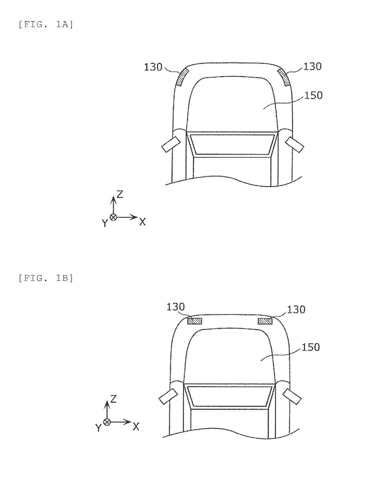
[0047]FIGS. 1A and 1B are plan views that each show positions of illumination apparatuses 130 according to the first embodiment in automobiles 150. In FIGS. 1A and 1B, front edges of the automobiles 150 are shown.

[0048]As shown in FIGS. 1A and 1B, the illumination apparatuses 130 are placed on the left and right sides of the foreparts of the automobiles 150. For example, in FIG. 1A, the illumination apparatuses 130 are placed on diagonal parts of corners of the automobile 150. In addition, in FIG. 1B, the illumination apparatuses 130 are placed on parts of the automobile 150 that directly face the front.

[0049]It is required that, from the front view, the illumination apparatuses 130 emit homogenous light. For that reason, in the illumination apparatuses 130, it is favorable that the divergence of light is made broader in the horizontal direction than in the vertical direction so as to increase visibility to the persons and the oncoming cars.

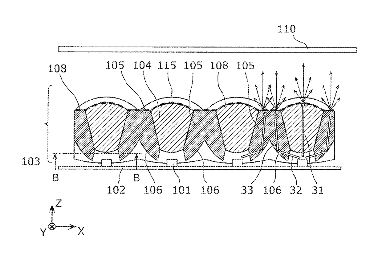
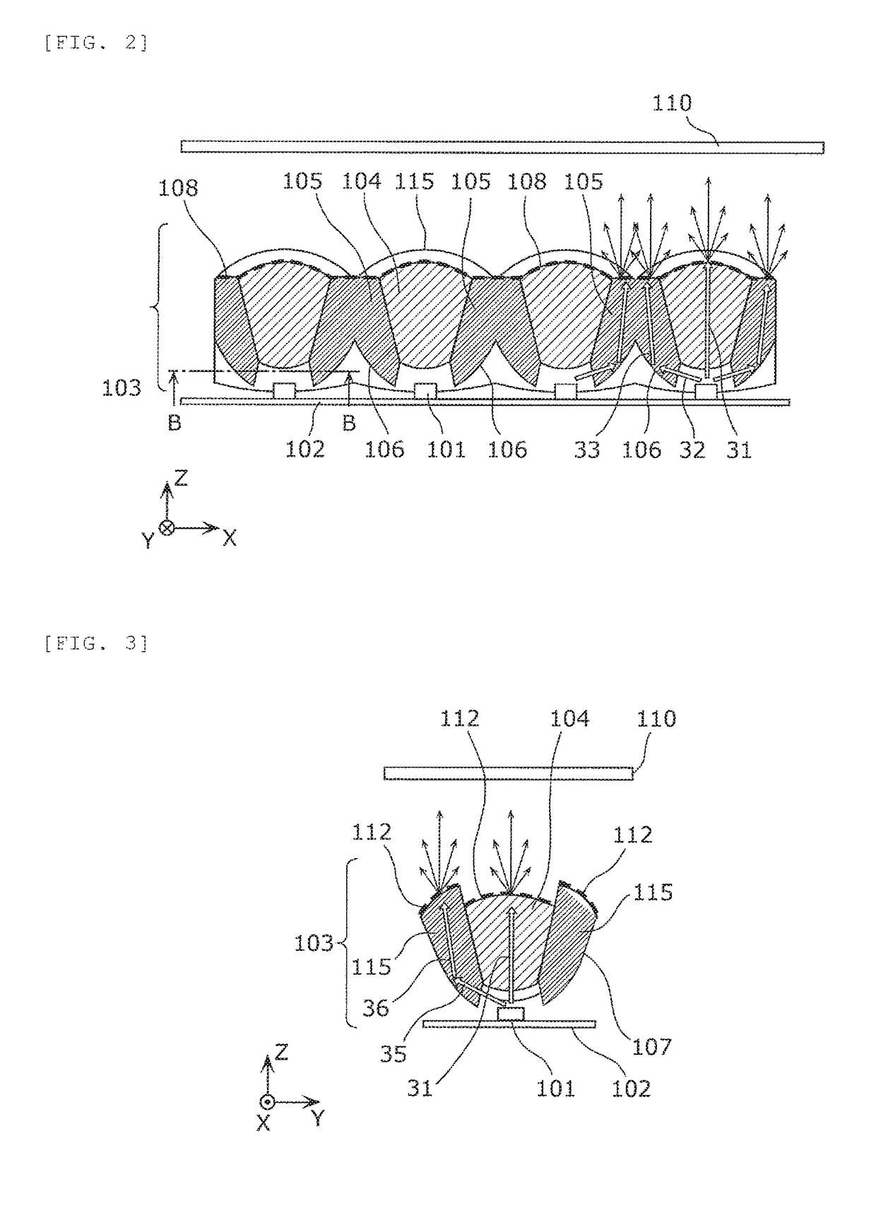
[0050]FIGS. 2 and 3 are cross-sect ion vie...


PUM


Abstract

An illumination apparatus including: multiple LEDs; and a lens unit that is placed correspondingly to the respective LEDs, wherein the lens unit includes a transmission lens, a first total-reflection lens, and a second total-reflection lens, wherein an incidence surface and an emission surface of the transmission lens, as well as incidence surfaces, emission surfaces and total-reflection surfaces of the first total-reflection lens and the second total-reflection lens are two-axis anamorphic aspherical surfaces, a microlens array is formed on at least one of the incidence surface and the emission surface of the transmission lens, a microlens array is formed on at least one of the emission surfaces, the total-reflection surfaces and the incidence surfaces of the first total-reflection lens and the second total-reflection lens, and the microlens arrays each have a structure in which microlenses are periodically arrayed, and are arrayed along the vertical and horizontal directions of the illumination apparatus.

Description

CROSS-REFERENCE TO RELATED APPLICATIONS[0001]This application is a U.S. national stage application of the PCT International Application No. PCT / JP2015 / 000903 filed on Feb. 24, 2015, which claims the benefit of foreign priority of Japanese patent application 2014-036328 filed on Feb. 27, 2014, the contents all of which are incorporated herein by reference.TECHNICAL FIELD[0002]The present invention relates to an illumination apparatus, such as a vehicle lighting device, that has a solid light-emitting element such as a light-emitting diode (LED) serving as a light source, as well as an automobile equipped with the same. In particular, the invention relates to a vehicle lighting device (so-called a daytime running light (DRL); a daytime lamp) that causes drivers of other vehicles, pedestrians, etc. to visually recognize the presence of the user's own car in daytime, as well as an automobile equipped with the vehicle lighting device.BACKGROUND ART[0003]Currently, with regard to DRLs, a ...

Claims


Application Information

Patent Timeline
Patent Type & Authority Patents(United States)
IPC IPC(8): B60Q1/00G02B19/00F21W107/10
CPCF21S41/275F21S41/322F21S43/14F21S41/265F21S43/315F21S43/40G02B19/0061F21S43/26
Inventor FUKUI, ATSUSHIMOCHIDA, SHOHROHYAMAGUCHI, TAKAYUKIOGATA, TOMOYUKI
Owner PANASONIC INTELLECTUAL PROPERTY MANAGEMENT CO LTD
Why Eureka
Try Eureka