Liquid crystal display device with a partial reflector and a polarizer on the partial reflector and an electronic apparatus

a liquid crystal display and partial reflector technology, applied in the direction of mirrors, polarising elements, instruments, etc., can solve the problems of insufficient brightness in the transmissive mode and the efficiency of light utilization, and achieve the effect of excellent visibility

Active Publication Date: 2006-04-04
BOE TECH GRP CO LTD
View PDF5 Cites 4 Cited by
  • Summary
  • Abstract
  • Description
  • Claims
  • Application Information

AI Technical Summary

Benefits of technology

[0005]In a conventional transflective liquid crystal display device, in a reflective mode display, light incident on a liquid crystal panel passes twice through a liquid crystal layer during the time it is reflected by a reflective layer and emitted to the outside. Therefore, circularly polarized light is reflected by the reflective layer to reverse the rotation direction of the polarizing axis, for switching pixels. In this construction, in order to achieve light and dark displays in the transmissive mode, light incident on the liquid crystal layer from the lower substrate side must be converted to circularly polarized light. As a result, light incident on a polarizing plate on the upper substrate side is converted to circularly polarized light or linearly polarized light, and in the light display, a part (about a half) of the incident circularly polarized light is transmitted for the display. In this way, in the transmissive mode, the utilization efficiency of light incident on the liquid crystal layer is low, thereby causing the problem of failing to achieve sufficient brightness in the transmissive mode.

Problems solved by technology

In this way, in the transmissive mode, the utilization efficiency of light incident on the liquid crystal layer is low, thereby causing the problem of failing to achieve sufficient brightness in the transmissive mode.

Method used


Image

  • Liquid crystal display device with a partial reflector and a polarizer on the partial reflector and an electronic apparatus
  • Liquid crystal display device with a partial reflector and a polarizer on the partial reflector and an electronic apparatus
  • Liquid crystal display device with a partial reflector and a polarizer on the partial reflector and an electronic apparatus

Examples


Embodiment Construction

[0088]An embodiment of the present invention will be described below with reference to the drawings.

[0089](Liquid Crystal Display Device)

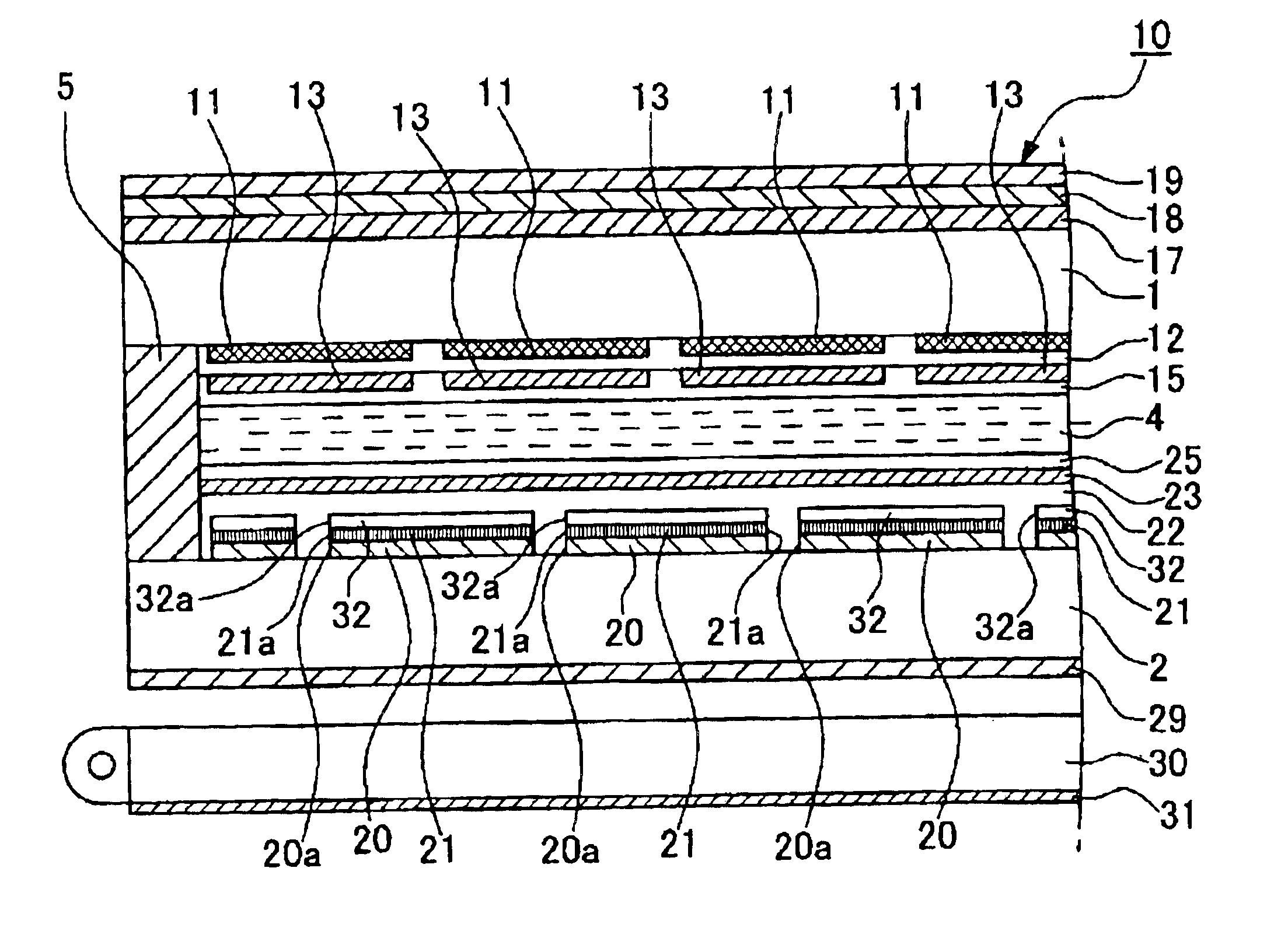
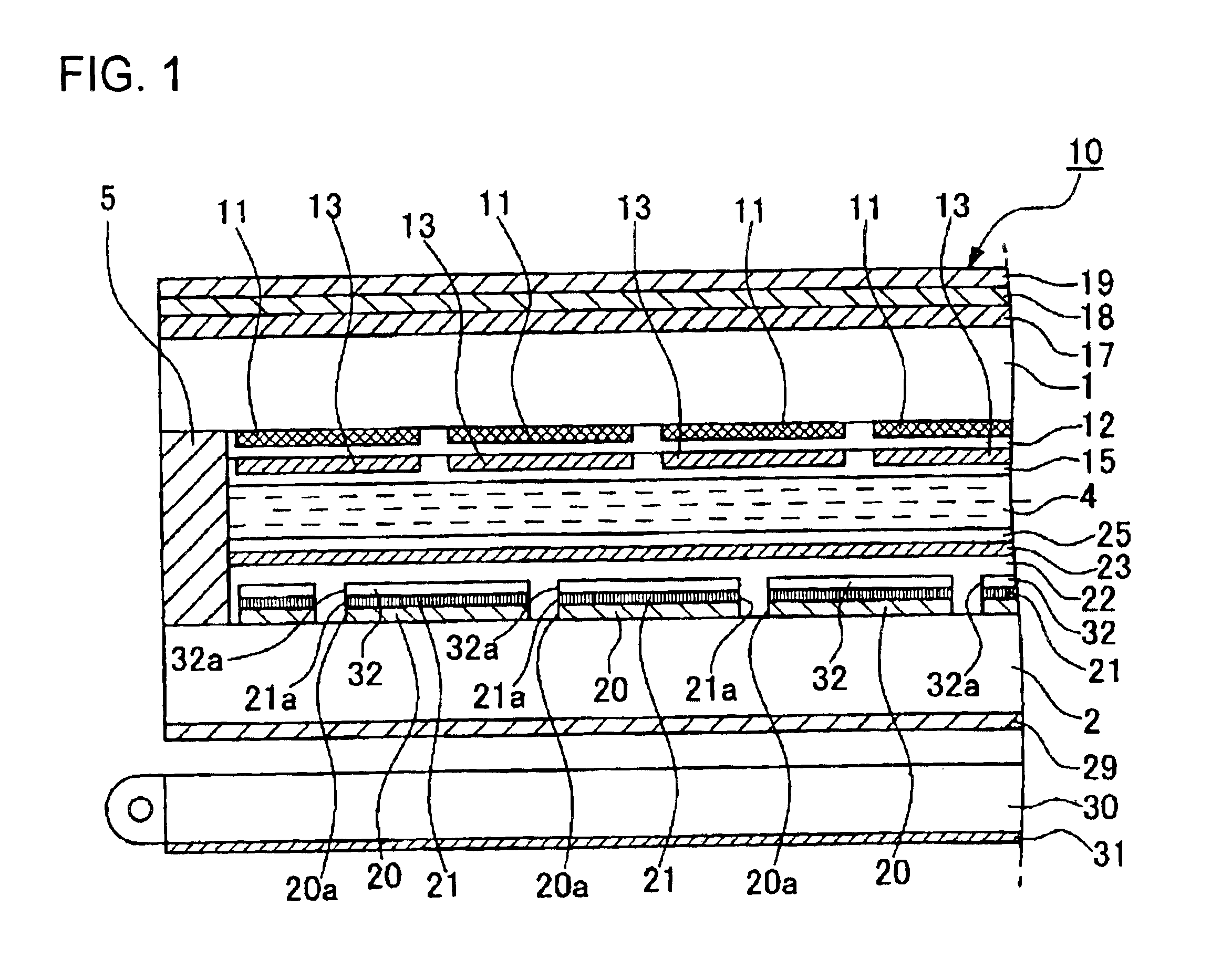
[0090]FIG. 1 is a partial sectional view showing a construction of a liquid crystal display device according to an embodiment of the present invention. The liquid crystal display device shown in the drawing schematically comprises a liquid crystal panel 10, and a back light (illumination device) 30 disposed at the back (the lower side of the drawing) of the liquid crystal panel 10. In this embodiment, a description is made of a case in which the present invention is applied to a passive matrix-type liquid crystal display device. In the each of the drawings, the thickness and dimensions of each component are appropriately changed for making the drawing easy to see.

[0091]The liquid crystal panel 10 comprises an upper substrate 1 and a lower substrate 2 which are opposed to each other, and a liquid crystal layer 4 sandwiched between the substrates 1 a...


PUM

PropertyMeasurementUnit
shapeaaaaaaaaaa
water-solubleaaaaaaaaaa
timeaaaaaaaaaa

Abstract

A liquid crystal display device of the present invention includes a liquid crystal panel including a liquid crystal layer 4-sandwiched between opposed upper and lower substrates, and upper and lower polarizing layers provided at the top and bottom of the liquid crystal layer-4, a reflective layer formed on the inner surface of the lower substrate and having through holes for transmitting light, a lower polarizing plate provided on the reflective layer, the lower polarizing layer having apertures which are continued from the through holes of the reflective layer and which are formed at substantially the same planar portions as the through holes. Therefore, the present invention provides a transflective liquid crystal display device capable of a light display even in a transmissive mode, and a manufacturing method therefor.

Description

BACKGROUND OF THE INVENTION[0001]1. Field of the Invention[0002]The present invention relates to a liquid crystal display device, a manufacturing method therefor, and an electronic apparatus. Particularly, the present invention relates to a construction of a transflective liquid crystal display device capable of a sufficiently light display in a transmissive mode, and a method of manufacturing a liquid crystal display device comprising the construction.[0003]2. Description of the Related Art[0004]In recent, a transflective liquid crystal display device has been put into practical use, the display device having a reflective mode for a display using external light such as natural light, illumination light, or the like, and a transmissive mode for a display using an illumination device such as a back light as a light source. A known example of such a transflective liquid crystal display device comprises a reflective layer provided inside a liquid crystal panel, for reflecting external ...

Claims


Application Information

Patent Timeline
Patent Type & Authority Patents(United States)
IPC IPC(8): G02F1/1335G02B5/02G02B5/08G02B5/30
CPCG02F1/133528G02F2203/09G02F2001/13356G02F1/133553G02F1/13356G02F1/1335
Inventor IIJIMA, CHIYOAKIHIRATA, YOSHITOMO
Owner BOE TECH GRP CO LTD
Why Eureka
Try Eureka