Magnetoelectric Coriolis force detection sensor

A technology for detecting sensors and Coriolis force, applied in the direction of steering induction equipment, etc., can solve problems such as no description or report found, and data not yet collected.

Active Publication Date: 2014-07-09
SHANGHAI JIAO TONG UNIV
View PDF8 Cites 20 Cited by
  • Summary
  • Abstract
  • Description
  • Claims
  • Application Information

AI Technical Summary

Problems solved by technology

[0003] At present, there is no description or report of the similar technology of the present invention, and no similar data at home and abroad have been collected yet.

Method used


Image

  • Magnetoelectric Coriolis force detection sensor
  • Magnetoelectric Coriolis force detection sensor
  • Magnetoelectric Coriolis force detection sensor

Examples


Embodiment 1

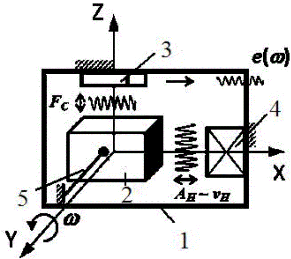
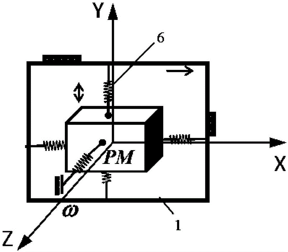
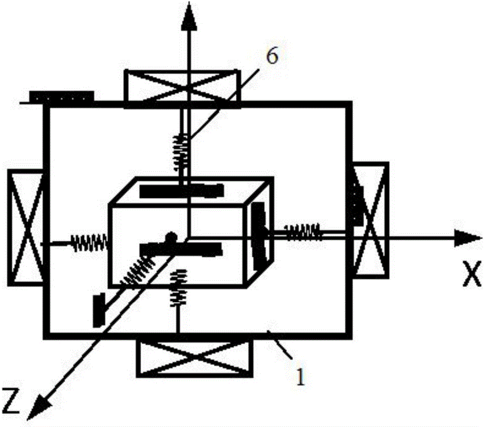
[0038] Such as figure 1 , figure 2 , image 3 with Image 6 As shown, this embodiment provides a magnetoelectric Coriolis force detection sensor, including a housing 1, a mass body 2 and a detection sensor mechanism 3 arranged inside the housing 1, and the housing 1 serves as a rotating system , with angular velocity Rotate, the mass body 2 at the speed Relative to the movement of the housing 1, the detection sensor mechanism 3 is used to realize angle detection.

[0039] Further, the mass body 2 is suspended in the three-dimensional space of the housing through a balance force.

[0040] Further, the balance force is provided by any of the following methods:

[0041] - elastic material body, one end of the elastic material body is fixed on any direction or any multi-directional end surface of the housing, the other end of the elastic material body is fixedly connected to the mass body, and the mass body is suspended under the constraint of the elastic material body ;...

Embodiment 2

[0057] The difference between this embodiment and Embodiment 1 is that the positions of the mass body and the electromagnetic coil are exchanged, that is, the electromagnetic coil in the center of the housing is used as an active excitation body (applying electromagnetic force), and the position of the electromagnetic coil on the end surface of the housing is The mass body produces relative motion, that is, the electromagnetic coil is both an active excitation body and a moving body, and its working principle is the same as that of embodiment 1.

Embodiment 3

[0059] On the basis of embodiment 1 or embodiment 2, the difference between this embodiment and embodiment 1 or embodiment 2 is that the detection sensor mechanism has the following structure:

[0060] -comprising a plurality of sensor units, the plurality of sensor units are respectively arranged on any one of the X-direction end surface, Y-direction end surface and Z-direction end surface of the shell, and / or, arranged on the X-direction of the mass block On any one of the end faces, the Y-direction end face and the Z-direction end face, simultaneous detection of an angle by multiple sensor units is realized.


PUM


Abstract

The invention provides a magnetoelectric Coriolis force detection sensor. The magnetoelectric Coriolis force detection sensor comprises a shell, a mass body disposed in the shell and a detection sensor mechanism disposed in the shell. The shell is adopted as a rotation system with an angular velocity shown as (omega vector). The mass body m moves relative to the shell at a velocity (velocity vector). The detection sensor mechanism is used for achieving angle detection. The magnetoelectric Coriolis force detection sensor achieves detection of low or high broadband rotating speed of a translational rotator (the shell) according to the Coriolis Effect. As Fc vector = - 2m[(omega vector)*(velocity vector)], when the m is established, the value of the Coriolis force is determined by the movement velocity (velocity vector) of a mass point (the mass body) and the angular velocity (omega vector) of the rotation system (the shell). Accordingly, when the (omega vector) is low (the translational rotator slowly rotates) or when the (omega vector) is high (the translational rotator rotates fast), optimized corresponding frequency spectrum relationship between the (omega vector) and the (velocity vector) can be obtained by correspondingly increasing or decreasing the movement velocity (velocity vector) of the mass point and the stable Coriolis force can be obtained, thus achieving detection of low-speed or high-speed rotation of the translational rotator.

Description

technical field [0001] The invention relates to the technical field of force detection sensors, in particular to a magnetoelectric Coriolis force detection sensor. Background technique [0002] We know that according to the theory of Newtonian mechanics, taking the rotating system as the reference system, the tendency of the linear motion of the particle to deviate from the original direction is attributed to the action of an external force, which is the Coriolis force and is defined as: In the formula is the Coriolis force; m is the particle mass; is the velocity of particle motion; is the angular velocity of the rotating system. [0003] Do not find description or report similar to the present invention at present, also do not collect similar data both at home and abroad. Contents of the invention [0004] The present invention provides a magnetoelectric Coriolis force detection sensor aiming at the above-mentioned deficiencies in the prior art. [0005] The pre...

Claims


Application Information

Patent Timeline
Patent Type & Authority Applications(China)
IPC IPC(8): G01C19/56
CPCG01C19/56
Inventor 杨斌堂孟光
Owner SHANGHAI JIAO TONG UNIV
Why Eureka
Try Eureka