Reticle increment calibration method for laser galvanometer system

A technology of laser galvanometer and calibration method, which is applied in the direction of measuring device, optical instrument test, machine/structural component test, etc. Accuracy and other issues to achieve the effect of reducing workload and reducing the impact of human factors

Inactive Publication Date: 2014-07-09
XI AN JIAOTONG UNIV
View PDF5 Cites 14 Cited by
  • Summary
  • Abstract
  • Description
  • Claims
  • Application Information

AI Technical Summary

Problems solved by technology

In the existing calibration method, it is first necessary to install the calibration plate or calibration paper to a specific position to ensure that the calibration surface is flush with the original plane, and then at least 9 points of calibration and calibration are required, which mainly rely on Calibration personnel observe to judge whether the laser spot or laser track coincides with the standard point or line, which has a large subjective and human factor, which may make the calibration accuracy not meet the requirements
[000

Method used


Image

  • Reticle increment calibration method for laser galvanometer system
  • Reticle increment calibration method for laser galvanometer system

Examples


Embodiment Construction

[0021] The present invention will be further described in detail below in conjunction with the accompanying drawings.

[0022] A crosshair incremental calibration method for a laser galvanometer system, comprising the following steps:

[0023] 1) First, open the calibration software and related files on the industrial computer of the laser galvanometer system that needs to be calibrated;

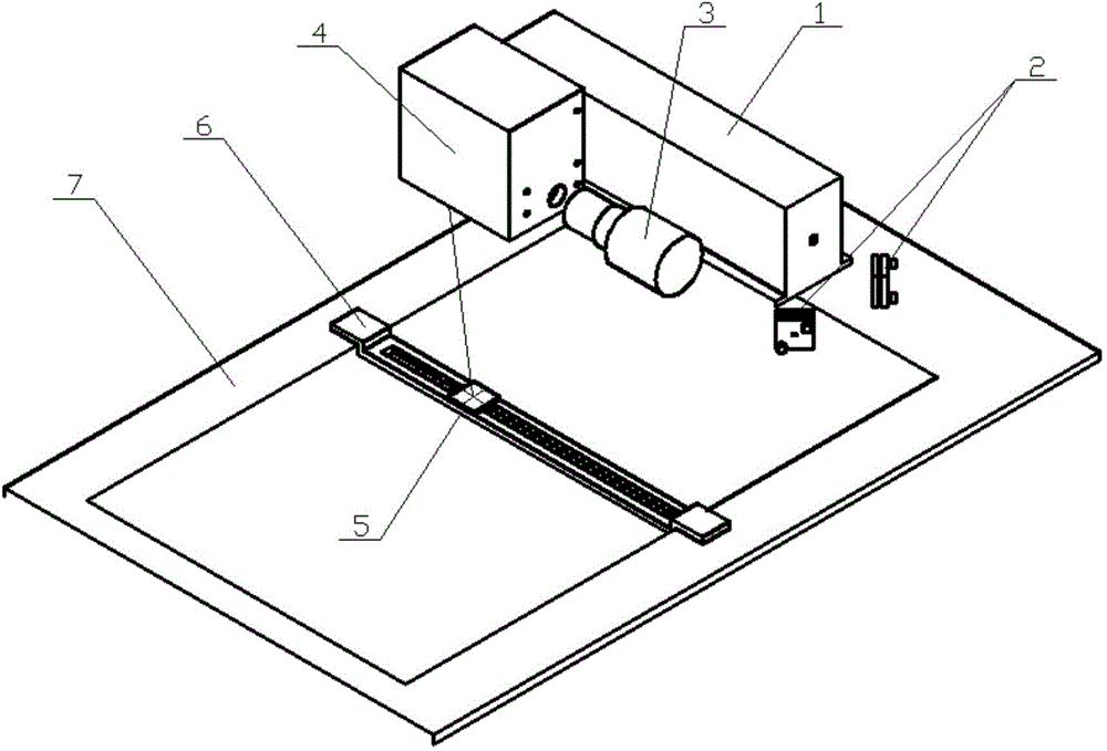
[0024] 2) Refer to figure 1 , turn on the power of the laser 1 to make it emit a laser beam, the laser beam enters the dynamic focus mirror 3 after being reflected by two reflectors 2, and then enters the scanning galvanometer system 4, adjusts the reflector 2, the dynamic focus mirror 3 and the scanning The installation position of the galvanometer system 4 enables the laser beam to be ideally focused on the plane 7;

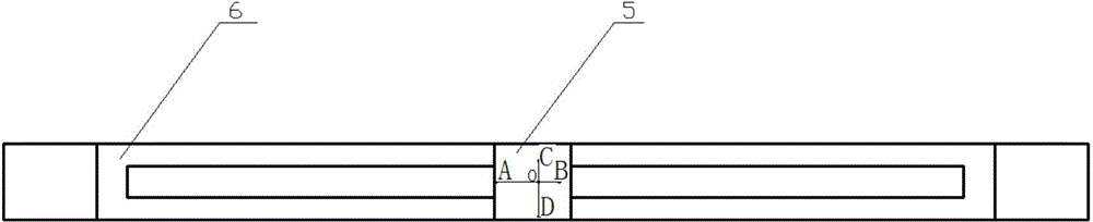
[0025] 3) Install the calibration device support frame 6 and the optical sensor 5 on the plane 7, and use gaskets to repeatedly adjust the height of the calibration device ...


PUM


Abstract

Provided is a reticle increment calibration method for a laser galvanometer system. A reticle increment scanning and optical sensor measurement analysis method is adopted, a traditional calibration target is not needed, only an automated measuring device simple in structure is needed, under the circumstance that calibration precision is guaranteed, influences of human factors are effectively reduced, and workloads are reduced; meanwhile, the method can be well applied to calibrating large-size planes.

Description

technical field [0001] The invention relates to the technical field of laser vibrating mirror systems, in particular to a crosshair incremental calibration method for laser vibrating mirror systems. Background technique [0002] The laser galvanometer system uses a laser as the light source, and the laser beam emitted by it passes through the scanning galvanometer and related optical devices, focusing on the plane, and the scanning trajectory of the laser on the plane can be controlled by the computer. Therefore, in the process of laser scanning, accurate scanning path is particularly important to ensure the trajectory accuracy. However, due to installation errors of lasers, scanning galvanometers and other related optical devices, alignment errors in optical path alignment, and defocus errors in the spot in the plane, etc., these will cause the laser beam emitted by the laser to not scan according to the ideal trajectory. . Therefore, usually before the laser galvanometer...

Claims


Application Information

Patent Timeline
IPC IPC(8): G01M11/00
Inventor 李涤尘杨春成曹毅同治强张莹莹
Owner XI AN JIAOTONG UNIV
Why Eureka
Try Eureka