
Method for measuring residual magnetic flux density of iron core of transformer

A magnetic induction intensity, transformer core technology, applied in the direction of magnetic performance measurement, etc., can solve the problem of difficulty in measuring the residual magnetic induction intensity of the iron core, etc.

Inactive Publication Date: 2014-07-09
YUN NAN ELECTRIC TEST & RES INST GRP CO LTD ELECTRIC INST +1
View PDF5 Cites 20 Cited by
  • Summary
  • Abstract
  • Description
  • Claims
  • Application Information

AI Technical Summary

Problems solved by technology

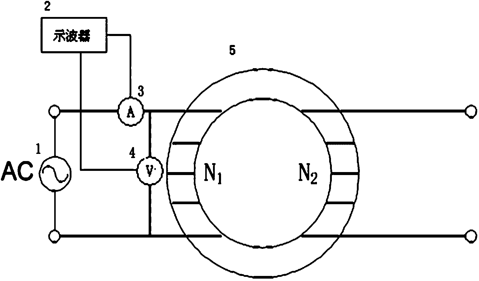
[0006] The present invention mainly aims at the problem of difficulty in measuring the residual magnetic induction intensity of the transformer iron core, and proposes a method for measuring the residual magnetic induction intensity of the iron core. After the equipment demagnetizes the transformer, whether the demagnetization effect meets the demagnetization requirements, so as to avoid damage to the equipment when the transformer is air-dropped

Method used


Image

  • Method for measuring residual magnetic flux density of iron core of transformer
  • Method for measuring residual magnetic flux density of iron core of transformer

Examples


Embodiment Construction

[0028] The problem to be solved by the present invention is achieved through the following technical solutions.

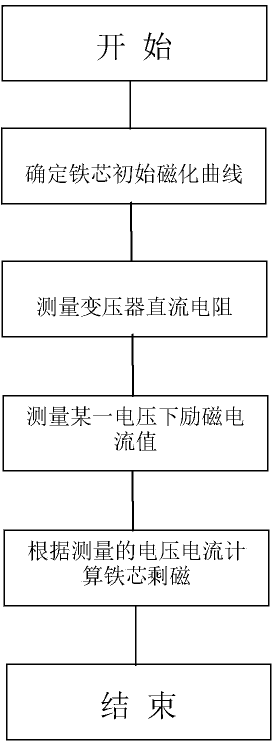
[0029] Implementation steps of the present invention are as follows:

[0030] The first step is to obtain the initial magnetization curve of the transformer core, which can be obtained from the core manufacturer or the transformer manufacturer;

[0031] The second step is to measure the DC resistance of the transformer, and measure the DC resistance of high voltage and low voltage respectively;

[0032] The third step is to measure the excitation current under a certain voltage of the transformer under test, determine the conversion of the magnetic field strength H of the iron core according to the excitation current, and obtain the magnetic induction intensity B of the iron core at this time by searching the initial magnetization curve;

[0033] The fourth step is to calculate the alternating magnetic induction intensity B at this time according to the effective ...


PUM


Abstract

A method for measuring residual magnetic flux density of an iron core of a transformer comprises the following steps that (1) an initial magnetizing curve of the iron core of the transformer is obtained; (2) the direct current resistance of the transformer is measured, wherein high voltage direct current resistance and low voltage direct current resistance are measured respectively; (3) the exciting current of the tested transformer at a certain voltage is measured, the magnetic field intensity H of the iron core is determined and converted according to the exciting current, the magnetic flux intensity B of the iron core at the moment is obtained by searching the initial magnetizing curve; (4) the size of the alternating magnetic flux intensity B1 at the moment is calculated according to an applied voltage effective value, and the residual magnetism Br of the iron core at the moment is obtained simply by subtracting the alternating magnetic flux intensity B1 from the magnetic flux intensity B obtained by using the initial magnetizing curve. The method solves the problem that the residual magnetic flux intensity of the iron core of the transformer cannot be measured, the residual magnetic flux intensity of the iron core is determined by using a mathematic method, the method can be widely applied to the detection of the demagnetizing effect of demagnetizing equipment after demagnetization is carried out by the demagnetizing equipment, and fundamental significance is achieved on the safe and stable operation of the transformer.

Description

technical field [0001] The invention relates to a method for measuring the residual magnetic induction intensity of a transformer iron core, which is suitable for detecting the residual magnetic induction intensity of the transformer after maintenance in a power grid and before airdropping, and belongs to the field of operation and maintenance of power transformation equipment. Background technique [0002] With the rapid development of my country's industrial economy, the demand for electricity is increasing rapidly, and the requirements for reliable power supply are also increasing. The power transformer is one of the important components of the power grid, and plays an extremely important role in the safe and reliable power supply of the power grid. However, in recent years, there have been many cases of transformer tripping and chromatographic abnormalities caused by airdropped transformers at home and abroad, affecting the reliability of power grid power supply, resulti...

Claims


Application Information

Patent Timeline
IPC IPC(8): G01R33/12
Inventor 邹德旭王耀龙钱国超徐肖伟周骏颜冰周仿荣
Owner YUN NAN ELECTRIC TEST & RES INST GRP CO LTD ELECTRIC INST
Learn More