Automatic power distribution network fault judging and controlling method of full-load switch ring main unit power supply
A distribution network fault and load switch technology, applied in the direction of electrical components, emergency protection circuit devices, etc., can solve the problems of different and complex switchgear, failure to achieve the application effect, etc., and achieve the effect of moderate investment cost
- Summary
- Abstract
- Description
- Claims
- Application Information
AI Technical Summary
Problems solved by technology
Method used
Image

Examples
Embodiment 1
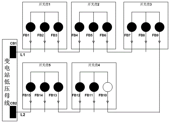
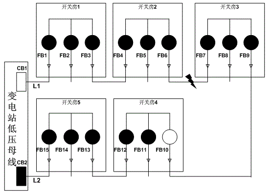
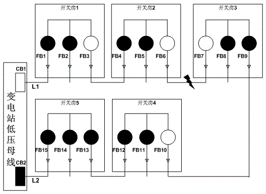
[0024] Assume that the power distribution cable network is grounded with small resistance, and the circuit breakers CB1 and CB2 of the substation are configured with a definite phase overcurrent protection delay of 0.3 seconds, and a definite time zero sequence overcurrent protection delay of 1.0 seconds. The time delay for the second overlap is 5 seconds. At this time, the ring network cabinet needs to be equipped with three-phase current transformers, zero-sequence current transformers, and incoming and outgoing line voltage transformers; the power distribution automation terminal is equipped with a unified definite time limit phase overcurrent judgment delay: 0.15 seconds, definite time limit zero sequence overcurrent Judgment delay: 0.5 seconds; configure a unified area outside the fault outlet switch to trip after 2 seconds of voltage loss delay, branch line fault branch line switch to trip after 2 seconds of voltage loss delay, non-faulty incoming line switch to trip afte...
Embodiment 2
[0038] Assume that the distribution cable network is: non-grounded or arc-suppression coil grounded, and the substation outlet circuit breakers CB1 and CB2 are configured with a fixed-time phase overcurrent protection delay of 0.3 seconds, and the primary and secondary overlap delays are both: 5 seconds . At this time, the ring network cabinet needs to be equipped with three-phase current transformers, zero-sequence current transformers, zero-sequence voltage transformers, and incoming and outgoing line voltage transformers; the power distribution automation terminal is equipped with a unified definite time limit phase overcurrent judgment delay: 0.15 seconds, Zero-sequence power direction to judge single-phase ground fault function; configure a unified fault outgoing line switch to trip after 2 seconds of voltage loss delay, branch line fault branch line switch to trip after 2 seconds of voltage loss delay, no fault incoming line switch to trip after 2 seconds of voltage loss ...
PUM
 Abstract
Description
Claims
Application Information