
Power factor correction circuit and control circuit and control method thereof

A technology of circuits and switching circuits, applied in the field of control circuits of power supplies, to achieve the effects of high power factor, convenient calculation, and easy realization

Active Publication Date: 2014-07-09
CHENGDU MONOLITHIC POWER SYST
View PDF4 Cites 20 Cited by
  • Summary
  • Abstract
  • Description
  • Claims
  • Application Information

AI Technical Summary

Problems solved by technology

However, the efficiency of existing PFC circuit products at low load conditions is not well in line with the expectations of energy regulatory agencies

Method used


Image

  • Power factor correction circuit and control circuit and control method thereof
  • Power factor correction circuit and control circuit and control method thereof
  • Power factor correction circuit and control circuit and control method thereof

Examples


Embodiment Construction

[0031]Specific embodiments of the present invention will be described in detail below, and it should be noted that the embodiments described here are only for illustration, not for limiting the present invention. In the following detailed description of the invention, numerous details are set forth in order to better understand the invention. However, it will be understood by those skilled in the art that the present invention may be practiced without these specific details. In order to clearly illustrate the present invention, detailed descriptions of some specific structures and functions are simplified herein. In addition, similar structures and functions that have been described in detail in some embodiments will not be repeated in other embodiments. Although terms of the present invention have been described in conjunction with specific exemplary embodiments, these terms should not be construed as being limited to the exemplary embodiments set forth herein.

[0032] The...


PUM


Abstract

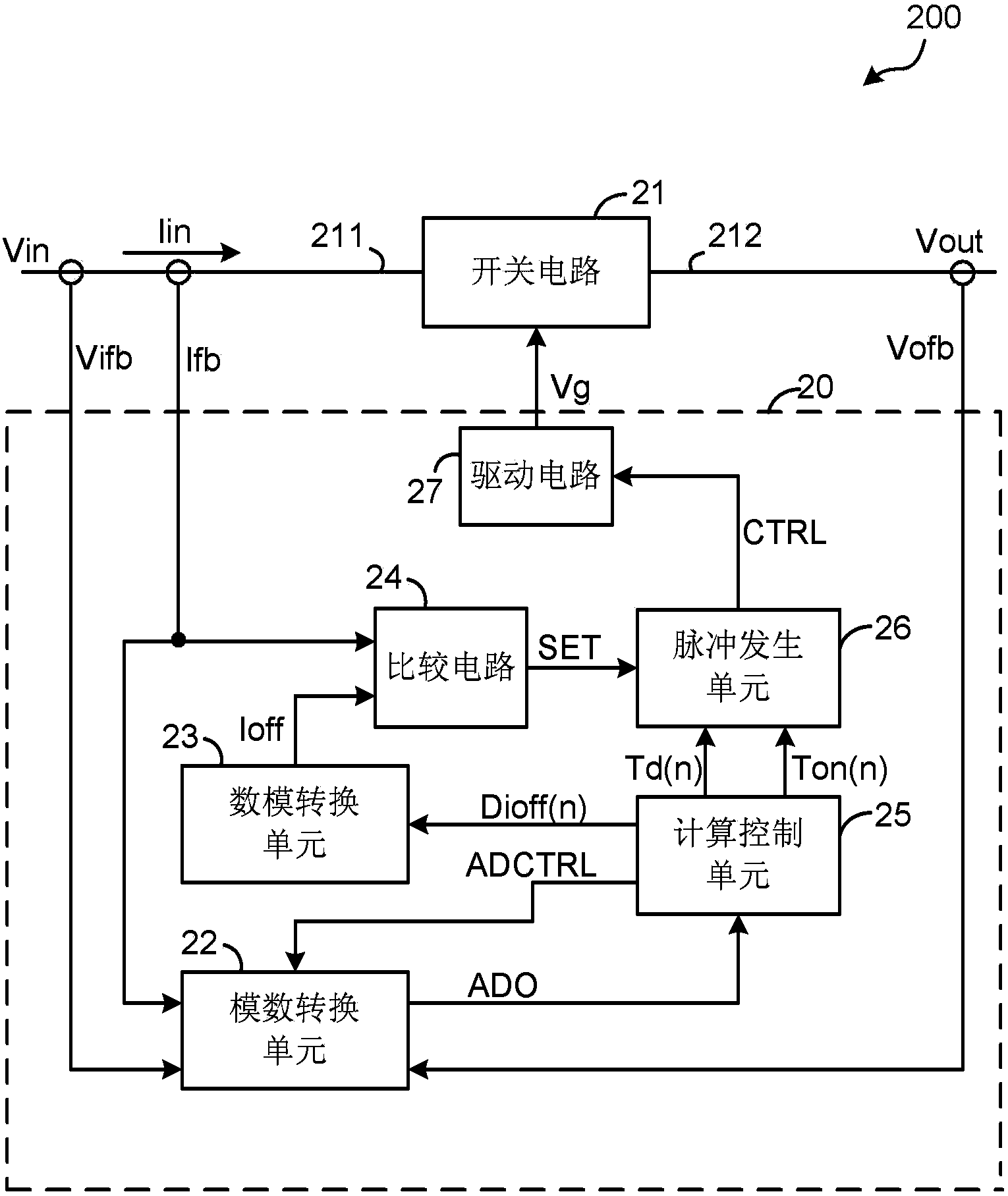
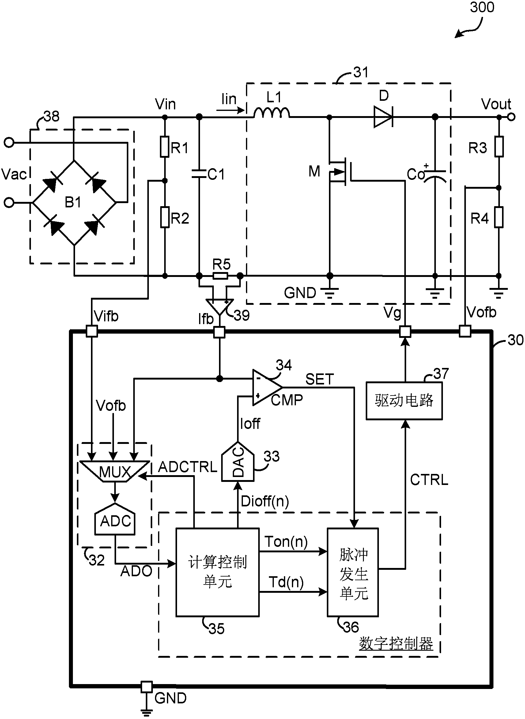
The invention discloses a power factor correction circuit and a control circuit and control method of the power factor correction circuit. The PFC circuit comprises a switch circuit comprising a main switch, an analog-to-digital conversion unit, a digital-to-analog conversion unit, a comparing circuit, a calculation control unit and a pulse generating unit, wherein the analog-to-digital conversion unit generates a sampling signal according to an input voltage, an input current and an output voltage; the digital-to-analog conversion unit provides a shutdown current reference signal; the comparing circuit generates a comparing signal according to the shutdown current reference signal and the input current; the calculation control unit provides starting delay time, expected switch-on time duration and a digital shutdown current referent signal according to the sampling signal; the pulse generating unit is coupled to the comparing circuit and the calculation control unit, the switch-on time of the main switch is controlled according to the comparing signal and a switch-on delay signal, and the switch-off time of the main switch is controlled according to the expected switch-on time duration. Calculation of the circuit is convenient to perform, and the circuit is easy to obtain and higher in efficiency and power factor in light loads compared with a traditional continuous current mode control method.

Description

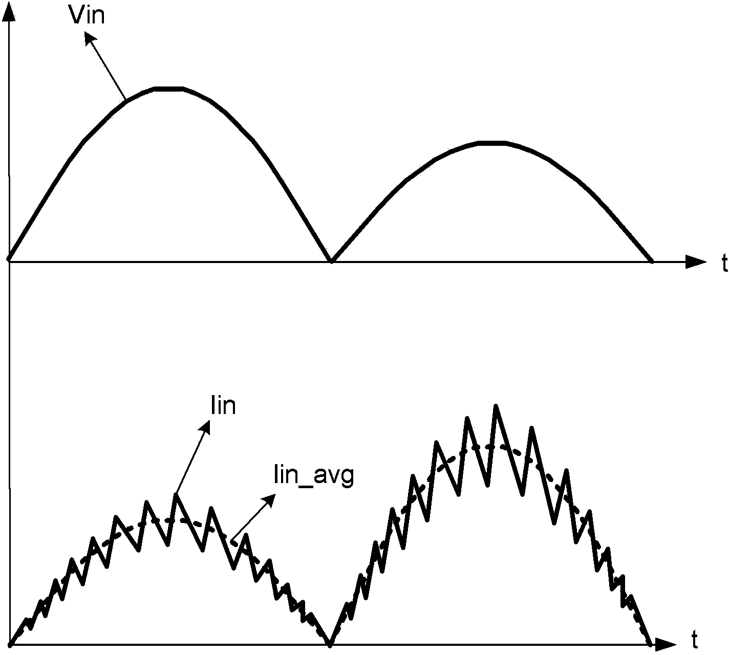
technical field [0001] The embodiment of the present invention relates to a control circuit of a power supply, in particular to a power factor correction circuit, a control circuit and a control method thereof. Background technique [0002] Power Factor Correction (PFC) circuits are widely used in power conversion systems to correct the phase of current and improve power factor. figure 1 A schematic diagram of a waveform of PFC control is shown. As shown in the figure, the input voltage Vin is in the shape of steamed buns, and the input voltage is generally obtained by rectifying the sinusoidal AC signal of the mains. In order to realize PFC control, it is necessary to control the waveform of the input current Iin to follow the waveform of the input voltage Vin, so that the phase of the input current Iin is consistent with the input voltage Vin. Generally, a higher input voltage Vin corresponds to a lower average input current Iin_avg. In the switch-mode PFC circuit, the ...

Claims


Application Information

Patent Timeline
Patent Type & Authority Applications(China)
IPC IPC(8): H02M1/42
CPCH02M1/4225Y02B70/10Y02P80/10H02M1/0019H02M1/0012
Inventor 林思聪陆文斌胡望淼姜礼节赵启明张广超
Owner CHENGDU MONOLITHIC POWER SYST
Learn More