A Method for Image Rendering Using Depth Map

A technology of image rendering and depth map, applied in image communication, stereo system, electrical components, etc., to reduce time complexity and improve quality

Active Publication Date: 2016-01-20
HUAZHONG UNIV OF SCI & TECH +1
View PDF4 Cites 0 Cited by
  • Summary
  • Abstract
  • Description
  • Claims
  • Application Information

AI Technical Summary

Problems solved by technology

The present invention directly solves the hole filling problem in the process of image drawing by combining image drawing with the process of filling holes

Method used


Image

  • A Method for Image Rendering Using Depth Map

Examples


Embodiment Construction

[0023] In order to make the purpose, technical solution and advantages of the present invention clearer, the present invention will be further described in detail below in conjunction with the accompanying drawings and examples. It should be understood that the specific examples described here are only used to explain the present invention, not to limit the present invention. Therefore, the technical features involved in the various embodiments of the present invention described below may be combined with each other as long as they do not constitute a conflict with each other.

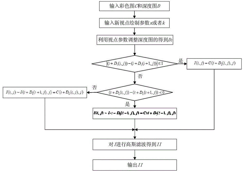
[0024] The image rendering method using the depth map of the present invention is as follows: figure 1 As shown, the specific implementation steps are as follows:

[0025] 1) Input the color image color map C, and the corresponding depth map D.

[0026] 2) Input the drawing parameters of the new viewpoint. Input the new viewpoint distance as the pixel distance x of the current viewpoint where the co...


PUM


Abstract

The invention relates to an image rendering method by utilizing a depth image. The image rendering method is characterized by comprising the following steps of (1) inputting a color image and the corresponding depth image, (2) inputting rendering parameters of a new viewpoint, (3) rendering the new viewpoint by utilizing the color image and the depth image to obtain a color image I, (4) performing post treatment on the color image I to obtain an image II and (5) outputting the obtained image II. According to the image rendering method, the process of image rendering and the process of hole filling are combined, and therefore the problem of hole filling is directly solved in the process of image rendering. In this way, the method not only can lower the time complexity of an algorithm but also can improve the quality of image rendering.

Description

technical field [0001] The invention belongs to the field of three-dimensional video processing, and in particular relates to an image drawing method using a depth map. Background technique [0002] DepthImageBasedRendering (DIBR) is the main method for virtual viewpoint synthesis in the field of 3D video processing. It uses the color map and its corresponding depth map to draw the virtual viewpoint. However, the disadvantage of viewpoint rendering based on DIBR is that holes inevitably exist in the rendered virtual image. The reason for the hole is that the coordinate mapping process is not a one-to-one relationship. Many coordinates in the virtual viewpoint do not correspond to the original color image, and appear as holes in the image. Therefore, in order to improve the quality of virtual viewpoint rendering, the generation of holes must be avoided. [0003] However, the general method of removing holes is to post-process the obtained virtual viewpoint, that is, to se...

Claims


Application Information

Patent Timeline
Patent Type & Authority Patents(China)
IPC IPC(8): H04N13/00
Inventor 杨铀于国星喻莉陈小平曾先敏
Owner HUAZHONG UNIV OF SCI & TECH
Why Eureka
Try Eureka