
Method for etching material longitudinally spaced from etch mask

一种蚀刻掩模、掩模的技术,应用在MEMS装置领域,能够解决表面微加工过程复杂性增加等问题

Active Publication Date: 2014-07-09
INVENSENSE
View PDF7 Cites 7 Cited by
  • Summary
  • Abstract
  • Description
  • Claims
  • Application Information

AI Technical Summary

Problems solved by technology

However, the complexity of the surface micromachining process generally increases as more layers are added to and subtracted from the substrate
Thick layers (such as rigid backplates in MEMS microphones) present further challenges to the microfabrication process

Method used


Image

  • Method for etching material longitudinally spaced from etch mask
  • Method for etching material longitudinally spaced from etch mask
  • Method for etching material longitudinally spaced from etch mask

Examples


Embodiment Construction

[0029] The illustrative embodiments enable micromachining processes to perform long-reach etching—that is, they mask openings spaced from the surface it etches. As a result, microfabrication processes can now fabricate improved and more robust MEMS devices. For example, the process improves state-of-the-art manufacturing processes to produce more robust dual-backplate MEMS microphones. Details of illustrative embodiments are discussed below.

[0030] figure 1 A mobile telephone 10 that may use a microphone configured and manufactured in accordance with an illustrative embodiment is schematically shown. It should be noted, however, that the discussion of the mobile phone 10 and the specific MEMS device (ie, microphone) is for illustration purposes only and thus is not intended to limit all embodiments of the invention. Accordingly, various embodiments are applicable to other microfabricated devices such as inertial sensors, gas detectors, network switches, etc...

[0031] B...


PUM


Abstract

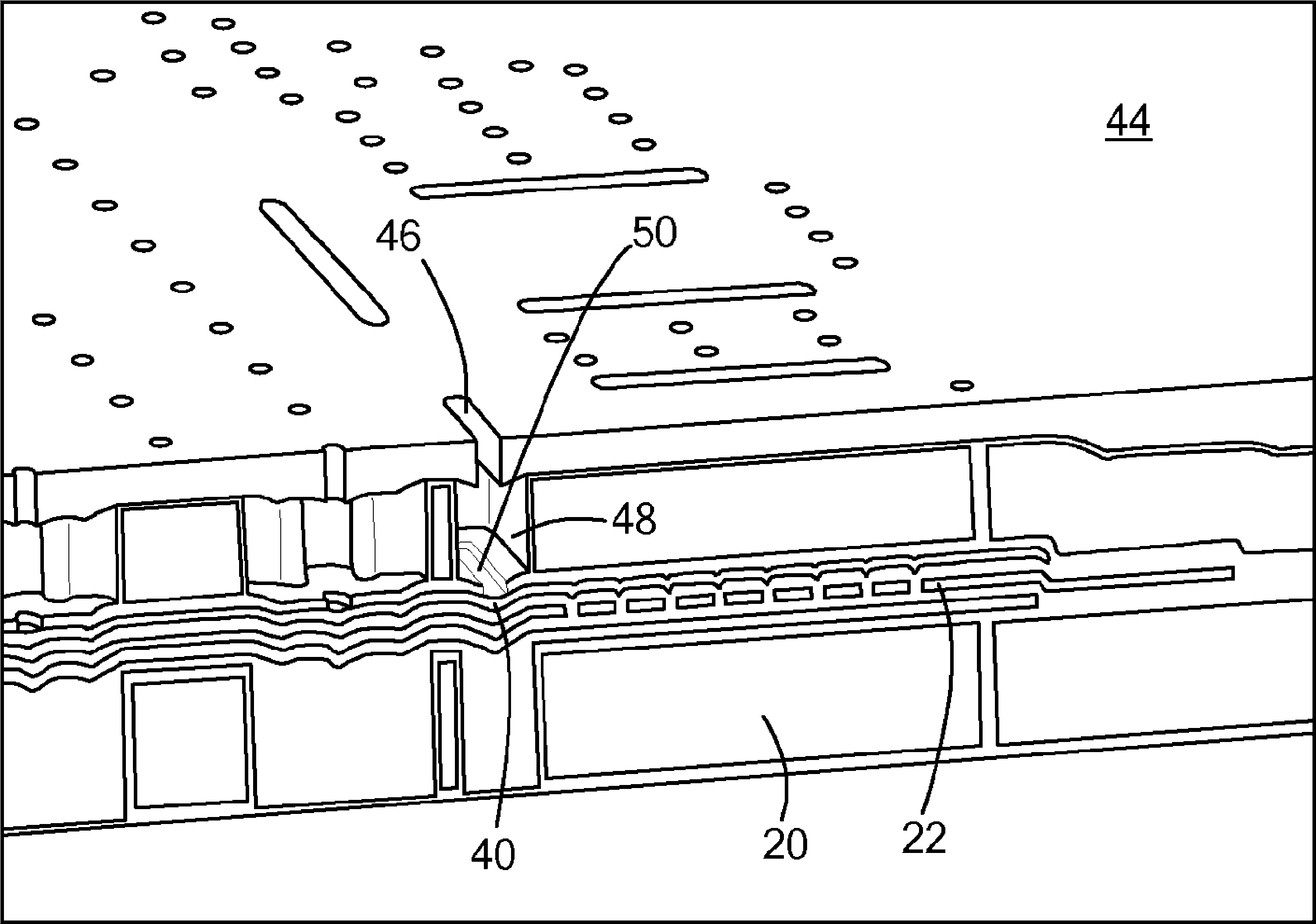
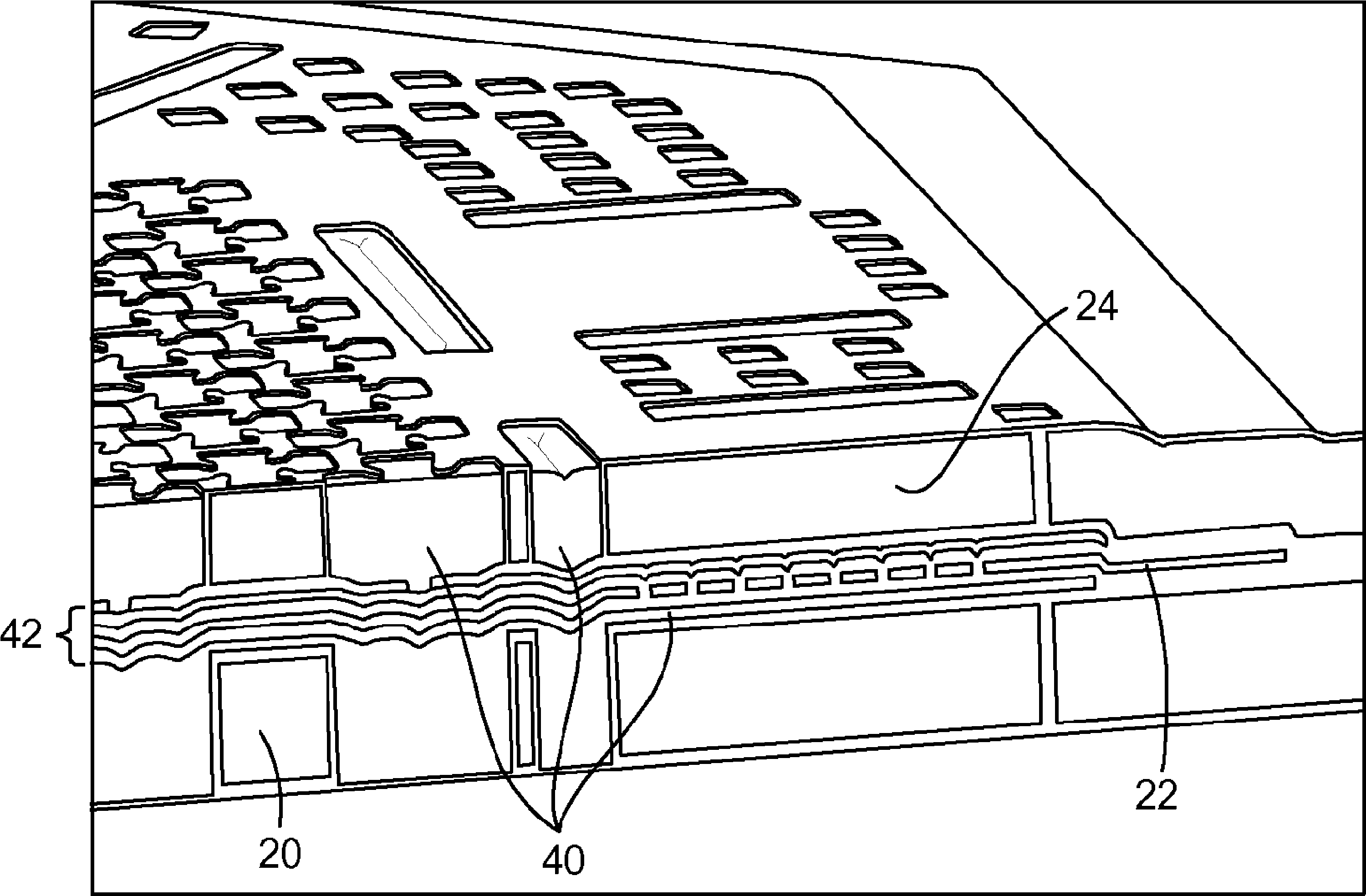
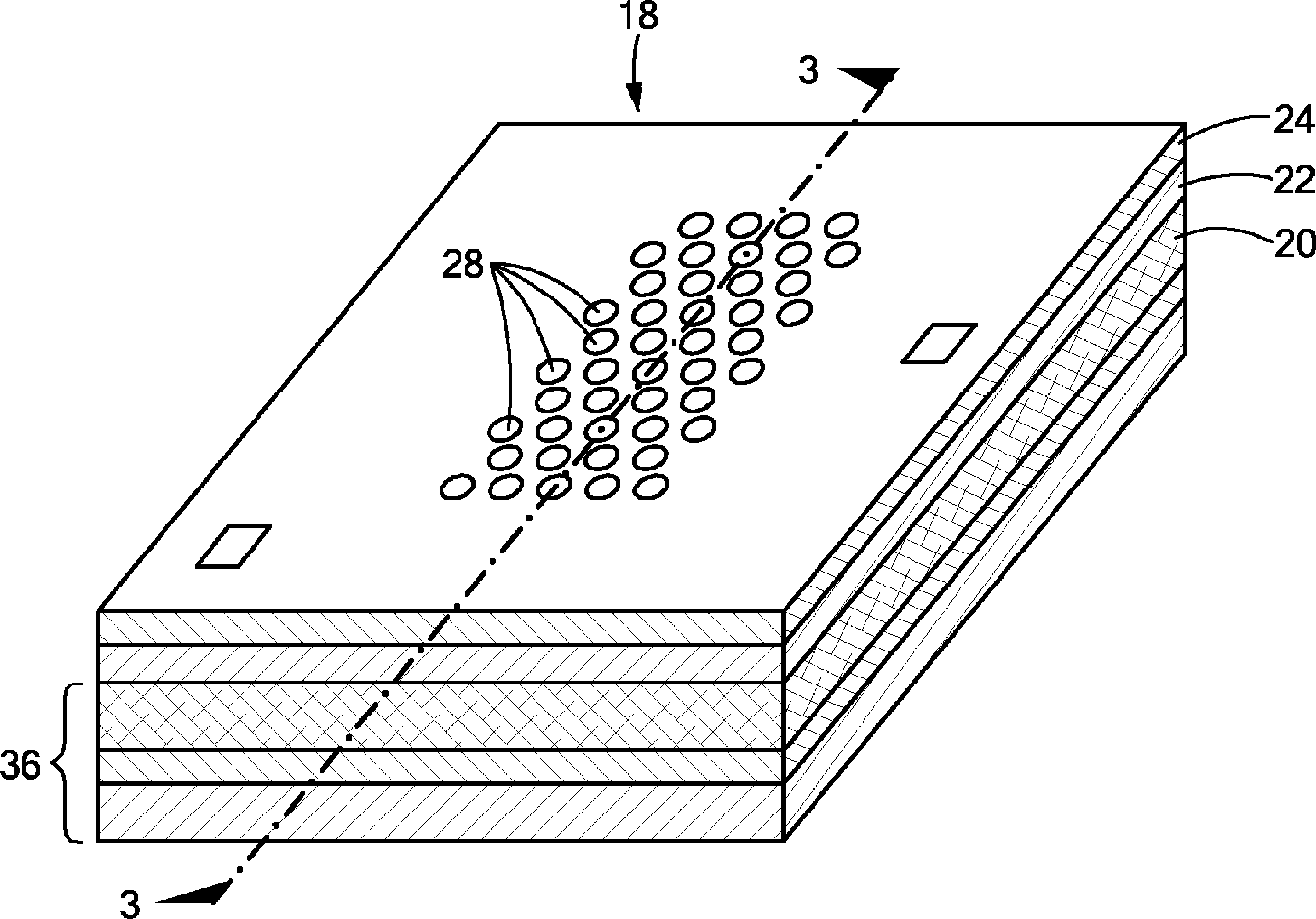
A micromachining process forms a plurality of layers on a wafer. This plurality of layers includes both a support layer and a given layer. The process also forms a mask, with a mask hole, at least in part on the support layer. In this configuration, the support layer is positioned between the mask hole and the given layer, and longitudinally spaces the mask hole from the given layer. The process also etches a feature into the given layer through the mask hole.

Description

technical field [0001] The present invention relates generally to MEMS devices, and more particularly, the present invention relates to processes for forming microfabricated devices. Background technique [0002] Microelectromechanical systems ("MEMS") are used in a growing number of applications. For example, MEMS are currently implemented as gyroscopes for detecting the pitch angle of aircraft, as microphones for use in mobile phones, and as accelerometers for selectively deploying airbags in automobiles. Briefly, such MEMS devices typically have a structure suspended above a substrate, and associated electronics that both sense movement of the suspended structure and communicate the sensed movement data to one or more external devices (for example, an external computer). The external device processes the sensed data to calculate the property being measured (eg pitch angle, incident acoustic signal or acceleration). [0003] As known to those skilled in the art, one com...

Claims


Application Information

Patent Timeline
Patent Type & Authority Applications(China)
IPC IPC(8): B81C1/00H04R19/00
CPCB81B2201/0257B81C1/00182H04R19/005H04R19/04H04R31/00H04R2499/11
Inventor K.L.杨T.D.陈
Owner INVENSENSE
Learn More